ragen-fio
Member
Ciao! I don't know if it is the right section, but in case of error please a moderator to move the discussion to the appropriate section, and sorry for my english! ")
Lately I have been interested in the delidding of the Cell using the most popular techniques such as paint spatulas, various blades and metallic objects, methods that seemed quite risky and slow although I managed to successfully delidding two processors.
Then I started thinking about some other methods, if not faster, at least safer, so I tried with the dental floss, sliding it between the IHS and the processor to cut the glue, but with great difficulty because it broke too much easily.
So I started to think about using some kind of quite resistant thin metal wire, until one day on AliExpress I saw the metal wire used to separate the LCD screens of smartphones and I immediately bought some rolls of various thickness 0.08mm and 0.1mm. What can I say?
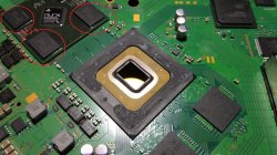
With the 0.08mm wire I delidded the Cell of a COK-002 in a very short time compared to spatulas and blades and with practically 0 risks, even if it is a tecnique that requires a little practice to prevent the wire from being break. Next time I'll try with the 0.1mm one maybe heating it with the special tip for the soldering iron.
I don't know if it is a method that has already been used, I have not found information about it, however I was pleased to share it with you.

Lately I have been interested in the delidding of the Cell using the most popular techniques such as paint spatulas, various blades and metallic objects, methods that seemed quite risky and slow although I managed to successfully delidding two processors.
Then I started thinking about some other methods, if not faster, at least safer, so I tried with the dental floss, sliding it between the IHS and the processor to cut the glue, but with great difficulty because it broke too much easily.
So I started to think about using some kind of quite resistant thin metal wire, until one day on AliExpress I saw the metal wire used to separate the LCD screens of smartphones and I immediately bought some rolls of various thickness 0.08mm and 0.1mm. What can I say?
With the 0.08mm wire I delidded the Cell of a COK-002 in a very short time compared to spatulas and blades and with practically 0 risks, even if it is a tecnique that requires a little practice to prevent the wire from being break. Next time I'll try with the 0.1mm one maybe heating it with the special tip for the soldering iron.
I don't know if it is a method that has already been used, I have not found information about it, however I was pleased to share it with you.
Last edited by a moderator: