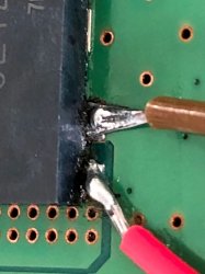
PS3 Fault finding YLOD with the SYSCON - First steps and Error reporting

HDMI IC removal:


SYSCON retest with HDMI IC removed from the board.

Going on with this subject...

HDMI IC resoldering... Long... with some issues, but finally got it done.
(I need to buy a "miniwave"/"minifala" soldering tip for this kind of repairs).
PS. Yeah.. I bet there will be some sarcastic comments after that video.
I tell you what... Do better than me. I work with the eq I have.. :)

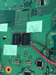
SYSCON retest with HDMI IC replaced (from doner board):
(please comment what do you think).

Short version:
#![INFO]: Connecting to Debug Device (SB UART)
# CODE CLOCK
# A0802124 FFFFFFFF
# A0802124 FFFFFFFF
# A0801002 FFFFFFFF


Long dump:
> auth
Auth successful
> ERRLOG CLEAR
FFFFFFFF Answer length
> errlog
00000000
OK 00000000
# CODE CLOCK
# FFFFFFFF FFFFFFFF
# FFFFFFFF FFFFFFFF
# FFFFFFFF FFFFFFFF
# FFFFFFFF FFFFFFFF
# FFFFFFFF FFFFFFFF
# FFFFFFFF FFFFFFFF
# FFFFFFFF FFFFFFFF
# FFFFFFFF FFFFFFFF
# FFFFFFFF FFFFFFFF
# FFFFFFFF FFFFFFFF
# FFFFFFFF FFFFFFFF
# FFFFFFFF FFFFFFFF
# FFFFFFFF FFFFFFFF
# FFFFFFFF FFFFFFFF
# FFFFFFFF FFFFFFFF
# FFFFFFFF FFFFFFFF
# FFFFFFFF FFFFFFFF
# FFFFFFFF FFFFFFFF
# FFFFFFFF FFFFFFFF
# FFFFFFFF FFFFFFFF
# FFFFFFFF FFFFFFFF
# FFFFFFFF FFFFFFFF
# FFFFFFFF FFFFFFFF
# FFFFFFFF FFFFFFFF
# FFFFFFFF FFFFFFFF
# FFFFFFFF FFFFFFFF
# FFFFFFFF FFFFFFFF
# FFFFFFFF FFFFFFFF
# FFFFFFFF FFFFFFFF
# FFFFFFFF FFFFFFFF
# FFFFFFFF FFFFFFFF

> bestat
00000000
# (PowerOff State)
# State = 00

> bringup
00000000
# [SSM] Bringup Start.
# [SSM] PS0 ok.
# [SSM] PS1 ok.
# [SSM] PS2 ok.

>
F0000003
# [SSM] PS3 ok.
# [SSM] PS4 ok.
# (PowerOn State)
OK 00000000
#!
#!Boot Loader SE Version 2.5.0
#!(Build ID: 3318,35708,
#!Build Date: 2008-10-11_00:31:58)
#!
#!Copyright(C) 2008 Sony Computer Entertainment Inc.All Rights Reserved.
#!
#![INFO]: Connecting to Debug Device (SB UART)
# [UCMD] Unknown command.

>
F0000003
# [UCMD] Unknown command.

> errlog
00000000
# CODE CLOCK
# FFFFFFFF FFFFFFFF
# FFFFFFFF FFFFFFFF
# FFFFFFFF FFFFFFFF
# FFFFFFFF FFFFFFFF
# FFFFFFFF FFFFFFFF
# FFFFFFFF FFFFFFFF
# FFFFFFFF FFFFFFFF
# FFFFFFFF FFFFFFFF
# FFFFFFFF FFFFFFFF
# FFFFFFFF FFFFFFFF
# FFFFFFFF FFFFFFFF
# FFFFFFFF FFFFFFFF
# FFFFFFFF FFFFFFFF
# FFFFFFFF FFFFFFFF
# FFFFFFFF FFFFFFFF
# FFFFFFFF FFFFFFFF
# FFFFFFFF FFFFFFFF
# FFFFFFFF FFFFFFFF
# FFFFFFFF FFFFFFFF
# FFFFFFFF FFFFFFFF
# FFFFFFFF FFFFFFFF
# FFFFFFFF FFFFFFFF
# FFFFFFFF FFFFFFFF
# FFFFFFFF FFFFFFFF
# FFFFFFFF FFFFFFFF
# FFFFFFFF FFFFFFFF
# FFFFFFFF FFFFFFFF
# FFFFFFFF FFFFFFFF
# FFFFFFFF FFFFFFFF
# FFFFFFFF FFFFFFFF
# FFFFFFFF FFFFFFFF

> powerstate
00000000
# ATA :ON
# PCI :OFF
# PCIex:OFF
# RSX :ON
# GDDR :ON
# XDR :ON
# EURUS:ON
# SB :ON
OK 00000000
# [SSM] Cond/Fatal received, msg=2663.
# [SSM] Fataldown Start.

>
F0000003
# [SSM] Fataldown ok.
# (PowerOff State) (Fatal)
# [UCMD] Unknown command.

> errlog
00000000
# CODE CLOCK
# A0802124 FFFFFFFF
# A0802124 FFFFFFFF
# A0801002 FFFFFFFF
# FFFFFFFF FFFFFFFF
# FFFFFFFF FFFFFFFF
# FFFFFFFF FFFFFFFF
# FFFFFFFF FFFFFFFF
# FFFFFFFF FFFFFFFF
# FFFFFFFF FFFFFFFF
# FFFFFFFF FFFFFFFF
# FFFFFFFF FFFFFFFF
# FFFFFFFF FFFFFFFF
# FFFFFFFF FFFFFFFF
# FFFFFFFF FFFFFFFF
# FFFFFFFF FFFFFFFF
# FFFFFFFF FFFFFFFF
# FFFFFFFF FFFFFFFF
# FFFFFFFF FFFFFFFF
# FFFFFFFF FFFFFFFF
# FFFFFFFF FFFFFFFF
# FFFFFFFF FFFFFFFF
# FFFFFFFF FFFFFFFF
# FFFFFFFF FFFFFFFF
# FFFFFFFF FFFFFFFF
# FFFFFFFF FFFFFFFF
# FFFFFFFF FFFFFFFF
# FFFFFFFF FFFFFFFF
# FFFFFFFF FFFFFFFF
# FFFFFFFF FFFFFFFF
# FFFFFFFF FFFFFFFF
# FFFFFFFF FFFFFFFF

> shutdown
00000000
# [SSM] Clearfatal Start.
# [SSM] Clearfatal ok.
# (PowerOff State)

> bringup
00000000
# [SSM] Bringup Start.
# [SSM] PS0 ok.
# [SSM] PS1 ok.
# [SSM] PS2 ok.

> errlog
00000000
# [SSM] PS3 ok.
# [SSM] PS4 ok.
# (PowerOn State)
OK 00000000
#!
#!Boot Loader SE Version 2.5.0
#!(Build ID: 3318,35708,
#!Build Date: 2008-10-11_00:31:58)
#!
#!Copyright(C) 2008 Sony Computer Entertainment Inc.All Rights Reserved.
#!
#![INFO]: Connecting to Debug Device (SB UART)
# CODE CLOCK
# A0802124 FFFFFFFF
# A0802124 FFFFFFFF
# A0801002 FFFFFFFF
# FFFFFFFF FFFFFFFF
# FFFFFFFF FFFFFFFF
# FFFFFFFF FFFFFFFF
# FFFFFFFF FFFFFFFF
# FFFFFFFF FFFFFFFF
# FFFFFFFF FFFFFFFF
# FFFFFFFF FFFFFFFF
# FFFFFFFF FFFFFFFF
# FFFFFFFF FFFFFFFF
# FFFFFFFF FFFFFFFF
# FFFFFFFF FFFFFFFF
# FFFFFFFF FFFFFFFF
# FFFFFFFF FFFFFFFF
# FFFFFFFF FFFFFFFF
# FFFFFFFF FFFFFFFF
# FFFFFFFF FFFFFFFF
# FFFFFFFF FFFFFFFF
# FFFFFFFF FFFFFFFF
# FFFFFFFF FFFFFFFF
# FFFFFFFF FFFFFFFF
# FFFFFFFF FFFFFFFF
# FFFFFFFF FFFFFFFF
# FFFFFFFF FFFFFFFF
# FFFFFFFF FFFFFFFF
# FFFFFFFF FFFFFFFF
# FFFFFFFF FFFFFFFF
# FFFFFFFF FFFFFFFF
# FFFFFFFF FFFFFFFF

> errlog
00000000
# CODE CLOCK
# A0802124 FFFFFFFF
# A0802124 FFFFFFFF
# A0801002 FFFFFFFF
# FFFFFFFF FFFFFFFF
# FFFFFFFF FFFFFFFF
# FFFFFFFF FFFFFFFF
# FFFFFFFF FFFFFFFF
# FFFFFFFF FFFFFFFF
# FFFFFFFF FFFFFFFF
# FFFFFFFF FFFFFFFF
# FFFFFFFF FFFFFFFF
# FFFFFFFF FFFFFFFF
# FFFFFFFF FFFFFFFF
# FFFFFFFF FFFFFFFF
# FFFFFFFF FFFFFFFF
# FFFFFFFF FFFFFFFF
# FFFFFFFF FFFFFFFF
# FFFFFFFF FFFFFFFF
# FFFFFFFF FFFFFFFF
# FFFFFFFF FFFFFFFF
# FFFFFFFF FFFFFFFF
# FFFFFFFF FFFFFFFF
# FFFFFFFF FFFFFFFF
# FFFFFFFF FFFFFFFF
# FFFFFFFF FFFFFFFF
# FFFFFFFF FFFFFFFF
# FFFFFFFF FFFFFFFF
# FFFFFFFF FFFFFFFF
# FFFFFFFF FFFFFFFF
# FFFFFFFF FFFFFFFF
# FFFFFFFF FFFFFFFF

> powerstate
00000000
# ATA :ON
# PCI :OFF
# PCIex:OFF
# RSX :ON
# GDDR :ON
# XDR :ON
# EURUS:ON
# SB :ON

> errlog
00000000
# CODE CLOCK
# A0802124 FFFFFFFF
# A0802124 FFFFFFFF
# A0801002 FFFFFFFF
# FFFFFFFF FFFFFFFF
# FFFFFFFF FFFFFFFF
# FFFFFFFF FFFFFFFF
# FFFFFFFF FFFFFFFF
# FFFFFFFF FFFFFFFF
# FFFFFFFF FFFFFFFF
# FFFFFFFF FFFFFFFF
# FFFFFFFF FFFFFFFF
# FFFFFFFF FFFFFFFF
# FFFFFFFF FFFFFFFF
# FFFFFFFF FFFFFFFF
# FFFFFFFF FFFFFFFF
# FFFFFFFF FFFFFFFF
# FFFFFFFF FFFFFFFF
# FFFFFFFF FFFFFFFF
# FFFFFFFF FFFFFFFF
# FFFFFFFF FFFFFFFF
# FFFFFFFF FFFFFFFF
# FFFFFFFF FFFFFFFF
# FFFFFFFF FFFFFFFF
# FFFFFFFF FFFFFFFF
# FFFFFFFF FFFFFFFF
# FFFFFFFF FFFFFFFF
# FFFFFFFF FFFFFFFF
# FFFFFFFF FFFFFFFF
# FFFFFFFF FFFFFFFF
# FFFFFFFF FFFFFFFF
# FFFFFFFF FFFFFFFF

> errlog
00000000
# [SSM] Cond/Fatal received, msg=2663.
# [SSM] Fataldown Start.
# [SSM] Fataldown ok.
# (PowerOff State) (Fatal)
# CODE CLOCK
# A0802124 FFFFFFFF
# A0802124 FFFFFFFF
# A0801002 FFFFFFFF
# A0802124 FFFFFFFF
# A0802124 FFFFFFFF
# A0801002 FFFFFFFF
# FFFFFFFF FFFFFFFF
# FFFFFFFF FFFFFFFF
# FFFFFFFF FFFFFFFF
# FFFFFFFF FFFFFFFF
# FFFFFFFF FFFFFFFF
# FFFFFFFF FFFFFFFF
# FFFFFFFF FFFFFFFF
# FFFFFFFF FFFFFFFF
# FFFFFFFF FFFFFFFF
# FFFFFFFF FFFFFFFF
# FFFFFFFF FFFFFFFF
# FFFFFFFF FFFFFFFF
# FFFFFFFF FFFFFFFF
# FFFFFFFF FFFFFFFF
# FFFFFFFF FFFFFFFF
# FFFFFFFF FFFFFFFF
# FFFFFFFF FFFFFFFF
# FFFFFFFF FFFFFFFF
# FFFFFFFF FFFFFFFF
# FFFFFFFF FFFFFFFF
# FFFFFFFF FFFFFFFF
# FFFFFFFF FFFFFFFF
# FFFFFFFF FFFFFFFF
# FFFFFFFF FFFFFFFF
# FFFFFFFF FFFFFFFF

> shutdown
00000000
# [SSM] Clearfatal Start.
# [SSM] Clearfatal ok.
# (PowerOff State)
 
Well, the videos were helpful. I can see you have good equipment. Question: Do you have an Oscilloscope? If so, you can probe VDDC and measure the noise to confirm bad tokins. Set scope to 50mV/div and 1uS, trigger at 1v. Noise should be under 50mVpp.

I would start with the troubleshooting the VDDC filter on both the CPU and RSX. First compare the resistance and ESR of the first stage RC filter. It amplifies the attenuation of the second stage (tokins). So if the first stage is bad, the whole filter will be detuned. and cause the 1002 error. It's easier to replace a couple of SMD's. Compare the values to the other 3-4 in the filter. Here's what I mean...
View attachment 34886
...The resistanc and ESR of those SMD's should match (within reason). If not replace and retest, before removing the tokins.

Stuff you get to skip thanks to the SYSCON UART Diagnosis (Imagine how much time that would have wasted):
  • ESR/resistance of the larger MLCC's next to the IOR VRM and the electrolytic caps. I'm sure they're fine or you'd get 1004 error and the RSX wouldn't start.
  • Compare the SMD components next to the Inductors to a known good board (to the left of the inductors in the pic above. May be different on a VER-001 IDK). There are more on the back side.
  • Check for voltage @ a few MOSFET in that section. The console wouldn't be booting this long or report a RSX OK PowerState if there were an issue here.
If the 1st stage filter is fine, then replace each tokin with 3x470uF Low ESR TaPol caps. I recommend Panasonic 2R5TPF470M6L or you can harvest them from dead motherboards. AlPol caps will work too, but they're theoretically not as good. You also need to bridge the + rails with at least 16AWG.


Maaaany thanks for these details!!!
That is really helpful!

PS. I don't have the oscilloscope, but... maybe I'd borrow one from someone local. I will see...
 
XX means wasn't there. Something wrong with cpu.Add photo so we can compare it.
I'll add it when I get home from work tonight. I appreciate your input.

Edit: You're right it wasn't used. I double checked the dev wiki and it's not there. Guess I'll stop chasing that lol.

Pro Tip: Press CTRL+F to search the PDF. Then write in the part (eg, R2001). It'll take you to everywhere in the schematic it's found. I wish it worked for Text too. It would be nice to be able to search for signal names and voltages, but you can't.

A0 2031 & 09 3003 were seen in a CPU with bump failures on the die due to heat damage (delamination). looked like a heat gun special. Anyway it can act like thermal error in RSX or CELL. Saw something similar with @botakompong when he had 2131 and changed the CPU set to fix it. We're still unsure if 2031 and 2131 are related, but they may be. 2030 is the same error, but for the CPU. You'll probably have to reball if the reflow didn't work. You did cover the hole in the PCB under the CPU with aluminum tape, right? Otherwise you probably didn't actually reflow the CPU. Just an FYI.
Yea, I definitely use control F as part of my regular process when using the schematic. I did not cover the hole in the PCB with aluminum tape when I reflowed it. I was not aware of that. So are you saying it might be worth attempting it again with using aluminum tape? I mean it's a dead board just sitting so not much to lose with it as of right now. I appreciate all of your advice. I've still got a lot to learn.
 
HDMI IC removal:


SYSCON retest with HDMI IC removed from the board.
I literally clapped when you used a paper towel to soak up the IPA/flux! So many people just scrub and spread it around. It annoys me to no end.

The issues you were having with the solder wick was due to the PS3's internal ground planes (7 layer board). The MB is it's own heatsink! You need to preheat the board. I find it's easier to work on an IR preheater, but using hot air to warm the area also helps. I use a T12-C4 tip for this, because it has a larger surface area.

Welp, you pretty much confirmed that 2124/2024 indicate HDMI encoder issues. If you notice the Step number in the errorlog, it's telling a story. 11 is early in the boot process. So during POST the PS3 is picking up that there is an HDMI error. You'll notice the 2124's mostly occur early in POST (step number 11). After replacing it, all your errors were in the 80 state.

At this point I'm just thinking out loud:

If the RSX is powering on, it's trying to power up the HDMI encoder via 1.5v_RSX_VDDIO. That goes to the 1.5v --> 3.3v level shifter (IC2501) and the RSX_initialize signal is being sent back to confirm it's getting power. Hypothesis #1 is that the Level shifter could be bad. Probe VCCA (1.5V) and VCCB (3.3v) while powering on to confirm it's working.

Also, 1.5v_RSX_VDDIO has a bunch of SMD's that could have shorted. This line is connected to a number of reset pins on the encoder before it gets to the level shifter. When the RSX powers up this might release the HDMI encoder out of reset simultaneously. If any of those SMD's is shorting, it's still held in reset.

The 2024's mostly occurred @ step number 80 (power on state). So if you aren't getting any 80 2024's that means the console isn't getting past POST+Bootloader. Something is preventing the RSX from starting, such as the tokins, BGA, bumps, RAM, or bad trace. So the lack of 80 2024's would be a bad thing. Since you were getting 80 2024 and 80 2124's, that's a good sign. And now we're back to the 80 1002/2124.

This hypothesis should be easy to test. Removing the level shifter, but leave a working HDMI encoder. See what error it generates. Then put the level shifter back and remove R2551. That should prevent 1.5v_RSX_VDDIO from powering either the HDMI reset circuit (preventing the encoder from tuning on) and the level shifter, resulting in more errors. That might help demystify these errors.

The 1002 is still annoying me. I really don't see how the HDMI encoder could cause it. It seems more likely to me that noise on VDDC is causing instability that could cause HDMI errors. I would start by confirming bad filter noise with my oscilloscope to be sure the tokins need replaced. Then If the 2124 persisted I'd start by comparing voltages and resistance of SMD's in the HDMI area to a working board. Then lookings at schematics and removing stuff systematically to characterize the errors generated and hopefully track it down.
 
Yea, I definitely use control F as part of my regular process when using the schematic. I did not cover the hole in the PCB with aluminum tape when I reflowed it. I was not aware of that. So are you saying it might be worth attempting it again with using aluminum tape? I mean it's a dead board just sitting so not much to lose with it as of right now. I appreciate all of your advice. I've still got a lot to learn.

Did you nudge it to be sure it flowed? If not, then you probably didn't get it to melt completely. It's worth a shot.
 
Did you nudge it to be sure it flowed? If not, then you probably didn't get it to melt completely. It's worth a shot.
I didn't nudge it but I did a very gradual heat increase kinda following NSC's method, going from roughly 350 c to 550ish c. I've always been a bit scared to nudge it thinking i'd throw off the alignment. Can't hurt as a last resort I suppose. You think it's possibly a bad IC maybe too? I know it's giving a A0A02030 code. If i'm reading this right wouldn't that point something at IC1101? or you think it's more CPU related. I was getting a A0302203, A0403034, and A0404003 before I hit the RSX and IC3001 with some heat. I was able to get those two error codes to go away after that interestingly enough... hmmm decisions, decisions. I'm just kinda hesitant to throw much more heat at this board since I got it down to just the A0A02030 code.

upload_2021-9-14_20-30-33.png


On a side note, I worked on my other CECHA model today and was able to get my error codes down to just a A0003001 code and it's not throwing any other codes now. I've swapped out two of the NEC's behind the RSX last week on it. I'm considering doing more. Has anyone been able to resolve the 3001 code by swapping these out by chance? I was reading some of the earlier posts and it sounded like that may be a possibility... Note: I did also attempt to put the console back together to confirm it wasn't just a 12 volt line error from not having the psu fully hooked up. Still yellow lighting.
 
Last edited:
The MB is it's own heatsink! You need to preheat the board. I find it's easier to work on an IR preheater, but using hot air to warm the area also helps. I use a T12-C4 tip for this, because it has a larger surface area.
I prefer J02, or B02 for IC leg soldering - but I don't have one at the moment :(
Awaiting shipping from aliexpress. :)

I don't have a handy preheater. I only have an IR-PRO-SC rework station, but it would be very hard to set it up together with the microscope in order to hmm.. work on it in a comfortable way.


I would start by confirming bad filter noise with my oscilloscope to be sure the tokins need replaced. Then If the 2124 persisted I'd start by comparing voltages and resistance of SMD's in the HDMI area to a working board. Then lookings at schematics and removing stuff systematically to characterize the errors generated and hopefully track it down.

I asked around and I will get an oscilloscope next week and will do all the tests.
Until then, I put this particular console on hold.

Again, many thanks for your cooperation on this.
Quite interesting!!
 
I didn't nudge it but I did a very gradual heat increase kinda following NSC's method, going from roughly 350 c to 550ish c. I've always been a bit scared to nudge it thinking i'd throw off the alignment. Can't hurt as a last resort I suppose. You think it's possibly a bad IC maybe too? I know it's giving a A0A02030 code. If i'm reading this right wouldn't that point something at IC1101? or you think it's more CPU related. I was getting a A0302203, A0403034, and A0404003 before I hit the RSX and IC3001 with some heat. I was able to get those two error codes to go away after that interestingly enough... hmmm decisions, decisions. I'm just kinda hesitant to throw much more heat at this board since I got it down to just the A0A02030 code.

View attachment 34889

On a side note, I worked on my other CECHA model today and was able to get my error codes down to just a A0003001 code and it's not throwing any other codes now. I've swapped out two of the NEC's behind the RSX last week on it. I'm considering doing more. Has anyone been able to resolve the 3001 code by swapping these out by chance? I was reading some of the earlier posts and it sounded like that may be a possibility... Note: I did also attempt to put the console back together to confirm it wasn't just a 12 volt line error from not having the psu fully hooked up. Still yellow lighting.
Well, that's your problem. A heat gun isn't accurate enough to work by itself. I prefer a hot air station myself, but if you can find a way to hold the heatgun in position and increase it's temperature in a controlled manner it could work. But you really need a thermocouple to know what the temperature is on the board! You can't do it from the temperature setting on the hot air gun/station itself. Those values are meaningless.

A slight nude will not move the chip enough to change the alignment. The solder adheres to the pads and springs back into position. If you nudge too much they can bridge to another ball. So don't knock the chip, just give it a slight nudge to see if it moves. I start nudging near 218C (LF) and 183C (Leaded) as measured by the therocouple next to the chip. It usually reads about 10-20C higher than that before the balls actually melt, because the temp probe isn't under the chip, it's exposed directly to the hot air. Nudging is the only way to know for sure the solder balls melt...I mean, without a calibrated reflow oven or BGA machine.

0A 2030 is CPU temp monitor error occurring immediately after reset. IC1101 is the Cell's thermal sensor chip. It isn't the actual thermocouple, that's on the die itself. The CPU sends the reading out to that chip, which interprets it. Usually that error is associated with BGA errors because of failed reflows or thermal stress. So that's why I think the CPU is probably not connected to the board properl, or dead. However, now I'm concerned about your RSX too, since I'm not confident in your reflow procedure. I was giving you the benefit of the doubt, because you have successfully reflowed before. But this heat gun nonsense and lack of nudging has me skeptical.

I just had a reballed console with leaded solder have another BGA failure! To be fair it broke in shipping/testing and I reflowed it using my process. 6 months was all I got out of that reflow. And I gave it every chance to work! Clearly reflows suck!
 
On a side note, I worked on my other CECHA model today and was able to get my error codes down to just a A0003001 code and it's not throwing any other codes now. I've swapped out two of the NEC's behind the RSX last week on it. I'm considering doing more. Has anyone been able to resolve the 3001 code by swapping these out by chance? I was reading some of the earlier posts and it sounded like that may be a possibility... Note: I did also attempt to put the console back together to confirm it wasn't just a 12 volt line error from not having the psu fully hooked up. Still yellow lighting.
3001 = 12v PWR failure, usually a bad PSU or blown fuse (F6001). Check schematic and use a multimeter to trace the path of 12v to where it stops. Check resistance between 2 prong on MB to be sure it's not shorting. If so, you'll have to fix the short or the fuse will blow again. 00 step number means it's not getting out of the PSU or past the first fuse on the board. The failure is occurring even before SYSCON reset. It doesn't even try, knowing it's hopeless.
 
Last edited:
Well, that's your problem. A heat gun isn't accurate enough to work by itself. I prefer a hot air station myself, but if you can find a way to hold the heatgun in position and increase it's temperature in a controlled manner it could work. But you really need a thermocouple to know what the temperature is on the board! You can't do it from the temperature setting on the hot air gun/station itself. Those values are meaningless.

A slight nude will not move the chip enough to change the alignment. The solder adheres to the pads and springs back into position. If you nudge too much they can bridge to another ball. So don't knock the chip, just give it a slight nudge to see if it moves. I start nudging near 218C (LF) and 183C (Leaded) as measured by the therocouple next to the chip. It usually reads about 10-20C higher than that before the balls actually melt, because the temp probe isn't under the chip, it's exposed directly to the hot air. Nudging is the only way to know for sure the solder balls melt...I mean, without a calibrated reflow oven or BGA machine.

0A 2030 is CPU temp monitor error occurring immediately after reset. IC1101 is the Cell's thermal sensor chip. It isn't the actual thermocouple, that's on the die itself. The CPU sends the reading out to that chip, which interprets it. Usually that error is associated with BGA errors because of failed reflows or thermal stress. So that's why I think the CPU is probably not connected to the board properl, or dead. However, now I'm concerned about your RSX too, since I'm not confident in your reflow procedure. I was giving you the benefit of the doubt, because you have successfully reflowed before. But this heat gun nonsense and lack of nudging has me skeptical.

I just had a reballed console with leaded solder have another BGA failure! To be fair it broke in shipping/testing and I reflowed it using my process. 6 months was all I got out of that reflow. And I gave it every chance to work! Clearly reflows suck!
I'm just working with the equipment I got man, and learning as I go with the information available to me. I never said I was an expert. I've had a few successful fixes. I do appreciate all your advice though. I'll definitely consider all of it for both consoles. I'd love to get a hot air machine at some point when I have the space and money to throw at it.
 
Last edited:
I'm just working with the equipment I got man, and learning as I go with the information available to me. I never said I was an expert. I've had a few successful fixes. I do appreciate all your advice though. I'll definitely consider all of it for both consoles. I'd love to get a hot air machine at some point when I have the space and money to throw at it.
I mean no offense. I'm a bit prejudiced against hot air guns for obvious reasons. My point was meant to come across as constructive criticism. To help you better your process by avoiding pitfalls I learned the hard way. Not to say you needed better equipment or to be an expert.

I'm no expert either, just figuring out as I go like all the rest. I have a ghetto setup filled with the cheapest Chinese parts I could afford...lol! But with practice an careful attention to details, and helpful tips from @squeept @vyktormvmpay25 @marciolsf @ElGris @Pacorretaco @NSC-Modz @sandungas and many others, I'm making it work for me. You'll learn how to make it work for you, with your specific equipment.

The real question is how far are you willing to take it? If you're just trying to fix 1 console, the PS3 can easily cost more to repair than to replace. How much time commitment, learning, reading, watching videos, troubleshooting, posting on the forums, and money is it worth to you? Are you doing it for fun or profit? Do you feel bad selling a console for $300 you know will fail again in 6 months to a year or are you willing to spend more to fix it right? Those are the rhetorical questions you should to ask yourself before getting too far down this rabbit hole.

I have filled my house with too many of these consoles. I need to sell them off and regain my space and sanity! It's just I don't feel comfortable selling a console I'm not confident was repaired well. It's a conscience matter.
No hard feelings man. I appreciate all the advice you've taken the time to write out for me. Yea for me, it's mostly become an obsession/hobby to want to learn more. I make a few bucks on the side, so far just selling working consoles that i got for cheap, then I do full clean-outs, swap the CMOS battery, and change the thermal paste. Sometimes package some bundles. Haven't actually sold any of the reflowed one's i've fixed so far. Those have become part of my hoarding stash for now since my 2 successful reflows i've done were both BC consoles. I've been playing ps3's since I first heard about the dongle jailbreak, then went thru all the stages from the cobra dongle onward. Took a few years off from playing games, was mostly focused on making music, but over the course of the pandemic learning repair became kind of a good distraction for me to stay sane. I spend a ton of time trying to learn as much as I can. I think I just generally enjoy fixing things. I'd love to get some actual training in it someday especially on the circuit board side of things. Again, I appreciate all the help you've given me so far as well as others on this site. I still got a lot to learn though for sure.
 
Last edited:
Hi there, just want to share a story about a YLOD SEM-001 from last weekend.

While I was waiting for some clamps to arrive to test the dead DIA-001, I want to have something to do so try another dead SEM-001 which was having 1002 errors. So assuming it's the tokin's problem, I decided to piggyback some electrolytic capacitors on it(as I don't have tantalum ones at hand). I didn't want to remove the tokins first because I wasn't 100% sure it's the exact problem. Instead I solder two jumper wires to the tokin's exposed pads and connect to a breadboard. I know it sounds ridiculous but I went ahead.

During the soldering, I found my hakko solder station was struggling with heating up the pads, especially the GND pad. It usually works great. I assume it has something to do with the massive ground copper around the motherboard, they soaked up all the heat. So I cranked the temperature up and finally managed to solder two jumper wires to the tokins' pads. I think it took me a dozen times to solder/resolder it and from touching the plastic case of the tokin you can feel the heat. At that time I wasn't too worried about the damage to the tokins thinking it might already dead.
nwOAjXu

kEJASoG

IMG_4991.jpg

IMG_4992.jpg

So I packed up and assembled the PS3 to a usable state. Hooking up 4 capacitors on a breadboard.
LNEudsd

MpUEiIH


And it works! Ridiculous but works.
IMG_4993.jpg

IMG_3686.jpg

The funniest thing is, later I decide to unplug the breadboard and see if the same error code shows up. But no, the SEM-001 PS3 just runs without turning yellow lights on. The only thing I did to the motherboard is soldering two jumper wires so it did prove some stories about heating up the motherboards can save the YLOD. It doesn't entirely "cure" the tokins, usually I get a yellow light after a cold boot, then press the power button again and it runs. Managed to run GT5 for 2 hours without problem.

That was the end of the story. A few questions arise:
- How do you remove the tokins and solder a replacement since the heat was dissipated very efficiently? A hot air rework station?
- Any recommendation sourcing the tokins (OE128)? I don't want to use tantalums although it might last longer but worse at filtering

EDIT: images
 

Attachments

  • IMG_4991.jpg
    IMG_4991.jpg
    68 KB · Views: 38
  • IMG_4992.jpg
    IMG_4992.jpg
    35.8 KB · Views: 36
Last edited:
This is my method. It works great and safe if you are careful.

I'm not convinced this is thermal panic, but Vitor has more experience working on non-BC models than I do. It's worth a shot, before you start using hot air on the board to replace IC's.

Thank you a lot for the instructions. I did a delidding to RSX on a 3034 COK-002 board, which the seller told me seal intact but appearently the RSX was reflowed, flux residuals everywhere, another story though...
IMG_5050.jpg

The question is, how I remove those thermal glue?? I watched quite a few guides and videos and none of them showed how to clean the four corners? Isopropyl alcohol only clears the centre. I guess some physical force is needed but I'm afraid of destroying it

UPDATE: For the IHS(metal plate) I found WD40 can be used to soften the glue, then rip it off using a plastic card. I'm not sure if it can be used on the chips though, it smells like kerosene
 
Last edited:
The question is, how I remove those thermal glue?? I watched quite a few guides and videos and none of them showed how to clean the four corners? Isopropyl alcohol only clears the centre. I guess some physical force is needed but I'm afraid of destroying it

UPDATE: For the IHS(metal plate) I found WD40 can be used to soften the glue, then rip it off using a plastic card. I'm not sure if it can be used on the chips though, it smells like kerosene
Physical abrasion! When it's still warm just use the edge of the IHS itself to scrape all but a thin layer of adhesive off. Best tool/methond I've found. I then clean with "Goof Off." It loosens/disolves the adhesive some, but only remove the left over thin layer. It takes too long to clean if you try to dissolve it all from the beginning.

I haven't tried WD40. I'll keep it in mind. Thanks for the tip!
 
Hi there, just want to share a story about a YLOD SEM-001 from last weekend.

While I was waiting for some clamps to arrive to test the dead DIA-001, I want to have something to do so try another dead SEM-001 which was having 1002 errors. So assuming it's the tokin's problem, I decided to piggyback some electrolytic capacitors on it(as I don't have tantalum ones at hand). I didn't want to remove the tokins first because I wasn't 100% sure it's the exact problem. Instead I solder two jumper wires to the tokin's exposed pads and connect to a breadboard. I know it sounds ridiculous but I went ahead.

During the soldering, I found my hakko solder station was struggling with heating up the pads, especially the GND pad. It usually works great. I assume it has something to do with the massive ground copper around the motherboard, they soaked up all the heat. So I cranked the temperature up and finally managed to solder two jumper wires to the tokins' pads. I think it took me a dozen times to solder/resolder it and from touching the plastic case of the tokin you can feel the heat. At that time I wasn't too worried about the damage to the tokins thinking it might already dead.
nwOAjXu

kEJASoG

View attachment 34906
View attachment 34908
So I packed up and assembled the PS3 to a usable state. Hooking up 4 capacitors on a breadboard.
LNEudsd

MpUEiIH


And it works! Ridiculous but works.
View attachment 34903
View attachment 34904
The funniest thing is, later I decide to unplug the breadboard and see if the same error code shows up. But no, the SEM-001 PS3 just runs without turning yellow lights on. The only thing I did to the motherboard is soldering two jumper wires so it did prove some stories about heating up the motherboards can save the YLOD. It doesn't entirely "cure" the tokins, usually I get a yellow light after a cold boot, then press the power button again and it runs. Managed to run GT5 for 2 hours without problem.

That was the end of the story. A few questions arise:
- How do you remove the tokins and solder a replacement since the heat was dissipated very efficiently? A hot air rework station?
- Any recommendation sourcing the tokins (OE128)? I don't want to use tantalums although it might last longer but worse at filtering

EDIT: images
You can buy new old stock NEC/TOKIN's. They are not going to perform like new, since they do degrade just sitting on the shelf, but they will work fine for quite awhile longer. I wouldn't worry about tantalum being inferior. They can provide sufficient noise reduction and will last longer.

For tokin removal, the easiest tool is a chisel edge exacto blade...
iu

No heat needed. But if you are intent on replacing with NOS TOKIN's then you may as well use hot air. The trick to that is preheating the board to 100C first using a IR PCB preheater like this...
71ARQ-eewDL._AC_SL1500_.jpg

...otherwise the ground plane will sink all the heat. That's the reason you found it so difficult to solder a connection to the GND rail. The PS3's 7-layer board is no joke!
 
Hello, i hope this is not a completely irrelevant question but does anybody know why the RSX dies?
Will all COK-01 and COK-02 machines eventually die? Is it the chip itself that has the flaw? Does temperature play it's part?

I mean we can try and change everything on the mobo but the thing is why? Maybe something else is happening over time that leads to RSX's death..temp could be it or not..i am just asking

If the above had been already answered please let me know.

Thanks.
Start here and read the next 2-3 pages. We had a rather entertaining discussion about that very topic. You may also be interested in this (particularly the FAQ).
 
Physical abrasion! When it's still warm just use the edge of the IHS itself to scrape all but a thin layer of adhesive off. Best tool/methond I've found. I then clean with "Goof Off." It loosens/disolves the adhesive some, but only remove the left over thin layer. It takes too long to clean if you try to dissolve it all from the beginning.

I haven't tried WD40. I'll keep it in mind. Thanks for the tip!
No worries. I learnt a lot from you. Mind the WD40 I only used on the IHS itself. I don't want to try it on PCB not to mention the RSX it could be corrosive. Contact cleaner maybe good?
 

Similar threads

Back
Top