db260179
Member
Ok, first steps good so far.
Second step is correct, the reason for the red flashing is because the eeprom checksum has now changed. This will be corrected once the internal mode is working ok for you.
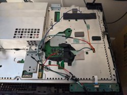
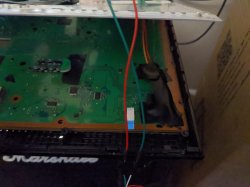
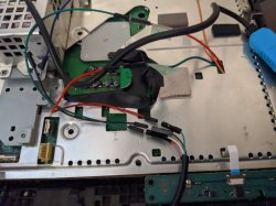
Could you upload photos of your connections to imgur.com
Also type in the terminal shell, 'dmesg' as i like to see what serial lead you are using and if any issues are occuring
One last thing, the thickness and length of the wire can affect the opertion. AWG 30 is probably the best, jumper wires works but i've found it to be too thick.
Also what i do, is turn off ps3 from mains switch, exit out of the python script, then re enter again, then power back on making sure the gnd from the serial lead is joined to the diag lead pin, then wait for a 10 seconds then try 'auth', serveral times it will get there eventually. Just keep trying several times
I havent tested on ubuntu 20.04, shouldnt be an issue, but maybe get a 18.04 livecd and try there, you can install packages on a livecd, just for testing purposes
Second step is correct, the reason for the red flashing is because the eeprom checksum has now changed. This will be corrected once the internal mode is working ok for you.
Could you upload photos of your connections to imgur.com
Also type in the terminal shell, 'dmesg' as i like to see what serial lead you are using and if any issues are occuring
One last thing, the thickness and length of the wire can affect the opertion. AWG 30 is probably the best, jumper wires works but i've found it to be too thick.
Also what i do, is turn off ps3 from mains switch, exit out of the python script, then re enter again, then power back on making sure the gnd from the serial lead is joined to the diag lead pin, then wait for a 10 seconds then try 'auth', serveral times it will get there eventually. Just keep trying several times
I havent tested on ubuntu 20.04, shouldnt be an issue, but maybe get a 18.04 livecd and try there, you can install packages on a livecd, just for testing purposes
So, my process goes as follows:
Now here's where I begin to get the errors
- Solder RxD, TxD to respective pins, cover with kapton tape and then electrical tape
- Attach GND to ground point. In this instance, I used the exposed edge of the PCB
- Power board
- Run Python script in CXR
- auth -> auth successful
- EEP GET 3961 01 -> 00000000 FF
- EEP SET 3961 01 00
- EEP GET 3961 01 -> 00000000 00
- Power off
I was, just one time, able to authorize myself during the CXRF script, but I got an ascii error before being able to check the checksum.
- Solder GND to DIAG
- Power board
- No flicker, just RLOD with three beeps (even on the first time. This didn't happen on the last board I diagnosed, flickered as per usual)
- Run Python script in CXRF
- I either get "scopen response invalid" or various "ascii...decode bye 0xXX" error