PS3 Fault finding YLOD with the SYSCON - First steps and Error reporting

It was for a while. Now it is more severe,
The PS3 booted, but displayed:
"Cannot start. The appropriate system storage was not found."
Then shutting down and starting up fixed it until switched off for longer/cooled down.
Oh wow, sorry then. I was confusing it with the GLOD symptom of two HDD light blinks and no more signs of life.

But yours seems like another weird problem. Is the hdd spinning up when the malfunction occurs? Could even be a 5v power issue. You mentioned something other related to USB too?
Though I fear we might be derailing the conversation
Cheers
Well, it's still kind-of ontopic, as my goal is to find the fault and fix my machine, using SYSCON logs and sort....
Yeah, checked the 12V-to-5V converter and 5V_USB and 5V_HDD rails, seemed fine. (the USBs have their own power switches controlled by a USB HUB IC, that i think only powers up, if connection established to it's host/SouthBridge (upstream) -- could not check better as those are in the underside)

Now it get through the bootloader again (one blip of HDD led) and after leaving to warm up until the syscon throttles the fan (74°C), it started up again.
BUT now I heard some small whine from around the USBs. The area was unusually hot and the 2 ceramic capacitors that are exposed through an opening were extremely hot ... and looking in the schematic, those are indeed in the BE VRM ... kind of fit the picture.
Now i need some replacements and check if that was the problem.

Would be nice to fix it as this has low mileage (only about 83days of operation) although wasn't stored too clean.

Yes, hopefully that could be the issue. From the beginning it sounded like something misbehaving in the 5v circuit.
Maybe you could try just removing the suspicious capacitors and test. They might be non-essential. Before replacement arrives. Also service manuals are available in case you weren't aware btw. It could help you find out what those capacitors are actually doing.

It also reminds me a bit of other funny console I have.
Feel free to check
https://www.psx-place.com/threads/not-dead-c-ps3-nlod.31921/

Though yea is certainly not the same. Mine seems to have the problem in the 5v standby circuit. Still fits the bucket of weird PS3 problems. Though I'm no proper technician or anything.

Cheers
I already have the service manual, and already said i checked the capacitors in the schematic.....
But investigating further revealed the VRM is smoking hot (60+°C on the "PSU side" rater than the component side) after just 1-2 minutes -- while the Cell itself does need about 10-20 min to reach that with the heatsink/fan attached ofcourse.

So it may be coil or one or more IP2003 chip(s)?
Pretty hard to diagnose as those are on the component side (where also the heatsink is) but the CELL and the RSX need heatsink otherwise instantly overheat (both delidded). Also, those are LGA socketed and the pins are not direcly exposed.
The VRM controller may be ok, as the Syscon does not get BE_POW_FAIL signal.
I see now sorry. I was consistently too quick to jump to help.
Then again, it's about helping you help yourself, and in general I guess you are making some progress one way or the other.
Maybe somebody else can help too or at least benefit from the conversation in the future.

After all I also came to this thread with one initial idea, but coming more from the average user perspective. I'm no technician or anything.

Cheers
 
I have a DYN-001 which shuts down randomly (green led > delayed and quick yellow led > 3 beeps > red blinking) it can do immediately or last an hour or two, I've already tried other power supplies, so I want to see the syscon error log before I go into the NEC-TOKIN replacement endeavor.

How do I find the necessary pads for a serial connection on my DYN-001?
 
Hello , finaly I managed to connect to PS3 . After calling the Auth comand and got auth succesfally. I call the errlog command . I recieve F0000006 error , if i Press the on key i recieve F0000003 error. The console is with GLOD by my opinion. The second alternative is that the ps3 cannot run on hdmi, I didint test it with AV, but try the reset mode
 
Hello guys, i just started trying to fix some broken ps3 fats. I bought the uart cable and installed Python and the needed modules but my cable has only 4 pins as one of them is +5v, so i dont see a yellow "diag" cable. Should i buy another type of uart cable ot mby i can strip the usb part and solder another cable to the board if there is a spot left. Do i need this step so i can access the error log? The fat model i am testing at the moment has all capacitors changed and stil has a 4-5 sec ylod so perhaps i can look for the problem otherplace with the help of syscon diagnosis.
 
Hello guys, i just started trying to fix some broken ps3 fats. I bought the uart cable and installed Python and the needed modules but my cable has only 4 pins as one of them is +5v, so i dont see a yellow "diag" cable. Should i buy another type of uart cable ot mby i can strip the usb part and solder another cable to the board if there is a spot left. Do i need this step so i can access the error log? The fat model i am testing at the moment has all capacitors changed and stil has a 4-5 sec ylod so perhaps i can look for the problem otherplace with the help of syscon diagnosis.
Don't use the red lead on the UART cable . This is a picture of how to connect and "talk" to a COK-001/002. The black & grey wires from the motherboard are connect to ground. First only connect the UART white, black & green wires to the motherboard white, black & green wires and set offset (external mode). Power off the motherboard, connect the motherboard red wire to ground (grey in picture) and run commands in internal mode.
 

Attachments

  • uart.JPG
    uart.JPG
    1.2 MB · Views: 113
Thank you very much. I read the pdf manual yesterday evening a couple times and it did strike me at some moment but i didnt know how to delete my comment.
Anyway my errorlog gives 3034 and 4432. I tried putting coins under the pressure plates but that didn't work. So i am going to try a reflow tomorrow as the reball costs the same as buying another piece.
 
Hello guys, its me again. Good news the reflow worked like charm. What i did was cut some aluminium foil as i left two rectangles for the cpu and gpu. I used 3 layers of foil to protect the other parts of the board from the heat gun and counted to 60 for each component, i also put some flux between the cpu/gpu and board (in the small gap). I guess we can confirm 3034 and 4432 errors are pcb related. What i see now is that the part with the on/off and eject buttons doesnt work and there is no diode light, is this related somehow to the changes i did using the syscon script in order to access the commands privilage. Should i change something before putting everything together ?
Thank you for this thread!!
 
What i see now is that the part with the on/off and eject buttons doesnt work and there is no diode light, is this related somehow to the changes i did using the syscon script in order to access the commands privilage. Should i change something before putting everything together ?
Verify that the ribbon/flex cable is fully inserted at both ends and that there are no broken pads on either end of the cable.
 
Hello guys, its me again. Good news the reflow worked like charm. What i did was cut some aluminium foil as i left two rectangles for the cpu and gpu. I used 3 layers of foil to protect the other parts of the board from the heat gun and counted to 60 for each component, i also put some flux between the cpu/gpu and board (in the small gap). I guess we can confirm 3034 and 4432 errors are pcb related. What i see now is that the part with the on/off and eject buttons doesnt work and there is no diode light, is this related somehow to the changes i did using the syscon script in order to access the commands privilage. Should i change something before putting everything together ?
Thank you for this thread!!
You mean the buttons/light board isn't working?
But you say the console works now, How did you turn the thing on then?

Or there's something i didn't understand.
What you may be saying sounds familiar actually
 
Last edited:
I have finally managed to get the syscon codes. I had two unopened YLOD BC consoles with COK-002 boards. On one system I got 4432 and 3034 , another one got 4422 and 3034. Seems like BGA issue on both...

So after completing diagnostics, should we change the byte thingy back to how it used to be ? I'm referring to "39FE 38 00"?

Btw, the guide is not exactly newbie friendly. Most of us are not using Linux. And the whole thing with Python is quite a mess...Thankfully reading the NEC/Tokin thread and thanks to the user Rip-Felix has clarified it. But yeah, I definitely wished there was a guide for Windows users to begin with.
 
When i was reading the pdf guide i also thought there are some sentences a bit confusing, also as far i remember i found a couple of mistakes/typos that i could report, but i didnt because i think the whole guide needs a rewriting

I cant do it, and im not asking anyone to do it, but well... this requires someone nativelly english speaking, with some skills in resuming concepts in short descriptions, using the most intuitive words (and noob friendly) if posible, etc...

Also, is required some experience with this and a basic knowledge of how it works, but right now we cant say anyone is an expert with syscon... we are just in an experimental stage of the research

So considering all this... i think the best way to create a nice guide would be if some of you starts a new thread in the forum for it, and plaster a big warning at top saying "this guide is under construction" (and keep it under construction indefinitivelly)
Also, invite all other readers to help in writing it... the feedback from the readers is very important because it can show you where are the "weak" points of the procedures explained in the guide
You know... if there is a step of the guide where everybody fails... probably it means that step worths to be rewritten ;)
 
Last edited:
hello everyone, i'm pretty new to all of this & decided to follow this guide to diagnosing my sem-001, but i had some questions before i get started.
1. for the sem-001 is there a specific ground pin on the board or do we solder to the exposed ground at the exterior?
2. does the console need to be fully re-assembled to run these tests?

thank you all for all of your great work so far btw!
Take a look at the "2nd generation" section of this wiki page:
https://www.psdevwiki.com/ps3/Service_Connectors#2nd_Generation

Everybody is soldering wires to the pads behind syscon, but the fact is most/all the retail PS3 motherboards have soldering pads to add a service connector, and that service connector includes the required pins for syscon UART access
Is just... we dont have the connector :D (but it can be added incase someone finds a supplyer for it), as far i see is intended to connect a ribbon cable in it
PS3_PinJIG_Connector_2nd_Generation_DIA-001.jpg

Anyway... my point is you should take a look at your SEM-001 motherboard to find where are located the (unpopulated) pads for that service connector
You can solder the wires in it, you just need 3 pins (see the pinout table in the wiki)
SC_TXD = pin 10
SC_TXR = pin 9
Diag mode = pin 7

For the ground wire i think is better to attach it to the copper border all around the motherboard, is a safe solder job... and as i was mentioning in some posts is not even needed to solder it, you can just attach it with an alligator clip

Same stuff with the DIAG pin btw, keep in mind the DIAG needs to be used as a button switch to change the syscon operation modes, you are going to need to connect it and disconnect the DIAG from ground many times... so is better to dont solder DIAG to ground permanently
Instead of that... you can solder the DIAG to an alligator clip, and attach the alligator clip to the border of the moterhboard when needed
Or... solder a button in between DIAG and GND... this way you can change syscon operation modes by pressing a button, pretty cool feature, a bit useless in long term but it gives bonus points for elegance :encouragement:
 
Last edited:
Can you run the RX and TX through a USB connection or are serial ports the only way to go?

So I started this thread to have a deep discussion about the YLOD on the PS3 (mostly FAT versions) and how to use the SYSCON to understand further what can be done to repair the ps3.

My main reason that drives me to do this is that I've seen alot of miss informed threads on how to fix YLOD ps3, there is alot of valid pointers but the basics have to be done first.

DISCLAIMER:

Before attempting this procedure, PLEASE PLEASE make sure you are confident in basic soldering and diagnostics, I will not be held responsible for you breaking your ps3!!!

NOT all PS3 boards have the known serial connection or capability to connect!!
So far - COK-001,002, SEM-001 and DIA-001,002 can be connected

READ THE GUIDE AND ASK QUESTIONS IN THIS FORUM, THANK YOU!

Ok, thats the disclaimer over and done with:

So in case everyone has missed a thread about the syscon discovery - https://www.psx-place.com/threads/s...oxao-what-does-it-mean.26148/page-10#comments


This thread will be more of a deep dive in using the syscon.

What I hope from this thread is that people contribute their error codes they get from their syscon and we can create a database of error code and whats issues are related to that error codes that come out of it.

So to get everyone started, I will share my first draft syscon connection guide:

This guide covers what tools to use, software to use and versions of PS3 boards (known to access syscon) with identification of pins to connect to.

As this thread grows overtime we should have a good grasp of the errors and what needs fixing to keep these old PS3 consoles alive.

SYSCON Guide

Further changes are in the git repo

https://github.com/db260179/ps3syscon

Please contribute on this git repo in the issues section
New error messages, python script improvements
NOT PERSONAL SUPPORT ISSUES!

In this guide we will be:

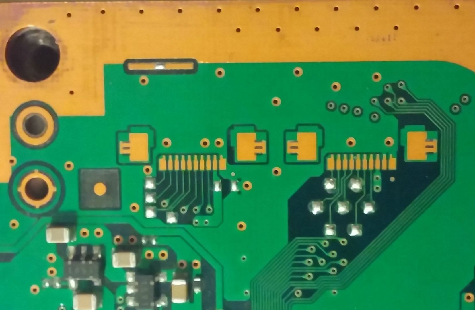
  1. Identfy the motherboard and its pins - RX, TX, GND and DIAG pin
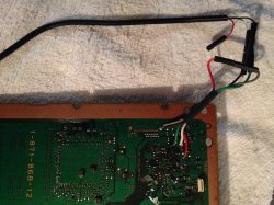
  2. Solder the jumper cables to the correct pins - RX, TX and GND go to the USB uart serial cable and DIAG get shorted to GND once the eeprom has set its mode to allow diag mode
  3. Run python syscon script to interact with the syscon - 'auth' command is used to access the high level commands on the syscon, and internal and external commands to run actions.
  4. External commands - used mostly to do basic stuff - activate internal commands
  5. Internal commands - Spend most of our time running - 'errlog', 'bringup' and other common used commands to help identify YLOD issues.
  6. Identify the YLOD issue based on the error code - and investigate with basic multimeter - voltage checks, resistance etc
  7. Tweaked fantables - use supplied tweaks from the my gitrepo for each motherboard

Big thanks and shout out to Mina for his help and patience!

Recorded errors (errlog) in the syscon shell:

POWER ERRORS:

0003001 POW_FAIL

A0093004 RSX_POW_FAIL

A0201B02 RSX VRAM FAIL - Faulty vrams (core would read a 0.2 ohm reading)

A0093003 CELL_POW_FAIL

BE ERRORS:

A0213013 BE_SPI DI/DO ERROR - CELL not communicating to syscon via SPI (1.2V MC2_VDDIO and 1.2V BE_VCS no output) = Possible shorts on the line, check C4001 and trailing caps. Possible CELL dead?

A0213011 BE_SPI CS ERROR

A0203010 BE_INIT OR BE_POWGOOD OR CLOCK ERRORS

A0801200 CELL overheating - poor thermal paste or no heatsink attached

RSX ERRORS:

A0404002 RSX_SPI DI/DO ERROR

A0404411 - ERROR ON RSX SPI?

A0A02031 - Thermal monitor DI/DO not communicating to RSX (possible dead Diodes in RSX)

A0403034, A0404402,A0404411 - Poor BGA solder connections for RSX ( you will see errors like - [POWERSEQ] Error : BitTraining RSX:RRAC:RX0:GLOBAL1:RX_STATUS )

A0232102 - IC6301 faulty (1.5v RSX_VDDIO) or in that area

SB ERRORS:

A0302203 SB_SPI DI/DO ERROR

A0313032 SB_CLOCK OR INIT ERROR

A0902203 SB GLOD issues, system update to repair nand/nor hashes


OTHERS:

A0022110 MK I2C ERROR (OR OTHER CLOCK's ERRORS)

A0401001 - BE VRAM Power Fail. It can be NEC Tokins

A0401002 - RSX VRAM Power Fail. It can be NEC Tokins

A0402120 - HDMI Error (IC2502)

A0401301 - BE PLL Unlock

Please submit your full error messages and what you did to resolve that error!

Look at the git repo - 'syscon error log codes.pdf'
 
Can you run the RX and TX through a USB connection or are serial ports the only way to go?
The serial ports of the old desktop PC motherboards cant be used for this... just incase you was thinking in it, dont do it because works at 12v, or you will fry the PS3 motherboard

The only way is to connect with serial UART TTL (3.3v)
And the easyest way to do it is if you buy one of the USB adapters we was mentioning in the first pages of the thread
There are tenths of manufacturers building them and are very cheap (the cheapest we found was 1$ free shipping)
 

Similar threads

Back
Top