PS3 Frankenstein PHAT PS3: CECHA with 40nm RSX

ANY YLOD console with an HDMI cord plugged in while testing the console will generate a 2120. Unplug the HDMI and it'll disappear. I don't think it means anything about having the wiring right or wrong, unless the 2120 was there without an HDMI plugged in to begin with.

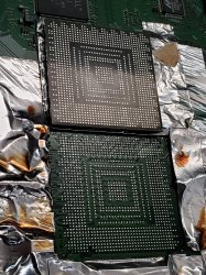
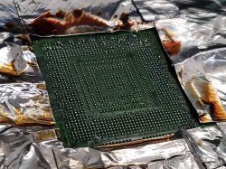
Sounds like the RSX didn't get soldered on correctly. I mean you were getting a GLOD before (one sign), and now 3034's (smoking gun). I think a reflow is called for.Also, I popped a BGA on a squeept reballed RSX by just soldering TaPol in, so the balls can be super delicate. Sounds like your console is teetering on a ball that sometimes connects mechanically depending on mounting pressure.

EDIT: If you're getting a picture. Your close! Try a bit more mounting pressure just to test the BGA defect and to see if the mod is working. Then you know all you need to do is reflow. Since you have some nice new leaded solder, the reflow should be strong. You won't need to reball again.

EDIT 2: Nevermind, if it's stable let it be! Picture us up. Oh, and.... CONGRAD...U...FREAKING...LATIONS MAN!!!
 
Last edited:
Here are some proofs. I reflowed it in the oven before this (board was kind of bent). But I think the problem wasn't even necessarily that, but a shady ground connection to the modchip. I just soldered a proper wire, not a blob of solder like they instructed (it sometimes got loose from slight pressure). Why I think it wasn't because of a reflow? Well, I checked the errors I was getting without the modchip before a reflow and after. They are identical. You will get a 3034 error without proper connection to the modchip. I will post the errors later. The RSX 's resistances are fine, and at the tokin it's a whooping 5 ohm. Ofc I conveniently already had a jailbroken hdd from the same system. Time to start up some games.
PRoof1.jpg
Proof2.jpg
 
Last edited:
...I reflowed it in the oven before this (board was kind of bent)...
That...um...was an interesting choice. I am constantly surprised by how something that should kill a PS3 somehow makes it come roaring back to life. I mean a working console is a working console, regardless of how ill advised the means that got you there were. I'm not going to condone the use of ovens, Ever! But if you want to go all Hansel and Gretel on your PS3, it's your property!
 
That...um...was an interesting choice. I am constantly surprised by how something that should kill a PS3 somehow makes it come roaring back to life. I mean a working console is a working console, regardless of how ill advised the means that got you there were. I'm not going to condone the use of ovens, Ever! But if you want to go all Hansel and Gretel on your PS3, it's your property!

You will be surprised how ghetto my bga station is. A proper electrical hazard... But obviously I don't recommend or advertise the way I do things. I'm well aware of the dangers, etc. The plan to improve it is still in progress. In fact , I am most likely just gonna order a proper station off Aliexpress at some point when my job situation improves.

The oven was a bit of a desperate attempt. It's a terrible choice, I agree. I obviously didn't feel good about it. But thinking I had nothing to lose at that point, anything goes. See, because I lack proper fixture on the preheater, which by the way is not wide enough to actually cover the whole board; it happens to warp. Soo, since the error was 3034 and I wasn't feeling so great about how uneven it looked, there was a chance it needed a reflow (Pretty much what you wrote, but I beat you to it). And performing another reflow so that it would warp again, well, that would slightly defeat the whole purpose. So I found several screws of equal length, secured them with nuts and put the board on a sheet pan, hoping that the green monster would warp slightly back to normal while being reflown at the same time. Ironically, like I've said before, it was most likely fine as it was. I only realized to redo the suspicious ground contact differently after the oven trick, not before. That's why it MAY seem like the reflow solved it, but it most likely had zero effect other than slightly fixing the warp...

Anyhow... At least now we know that the modchip is not a scam. I've lost around 2 weeks of my time and feeling the risk of failing several courses at the university now (luckily everything's online these days). But you know, if you dont play, you don't win :)

Below is the error code I got when I changed the necessary resistors and took the mod IC completely off. Also this was right before throwing the board into the oven. The same errors showed up after. You can use this as a reference for 65 nm RSX on COK002 (can't speak for COK001). It was an instant YLOD, but once you connect the mod IC correctly, it should switch on. And by the way it's probably wise to discard the previous codes I've been posting, since those happened when the modchip was either half connected or soldered wrong.

Code:
===================================
ERR 00: 00000000 A0403034 FFFFFFFF
ERR 01: 00000000 A0404002 FFFFFFFF
ERR 02: 00000000 A0403034 FFFFFFFF
ERR 03: 00000000 A0404002 FFFFFFFF
ERR 04: 00000000 A0403034 FFFFFFFF
ERR 05: 00000000 A0404002 FFFFFFFF
ERR 06: 00000000 A0403034 FFFFFFFF
ERR 07: 00000000 A0404002 FFFFFFFF
ERR 08: 00000000 A0403034 FFFFFFFF
ERR 09: 00000000 A0404002 FFFFFFFF
ERR 10: 00000000 FFFFFFFF FFFFFFFF
ERR 11: 00000000 FFFFFFFF FFFFFFFF
ERR 12: 00000000 FFFFFFFF FFFFFFFF
ERR 13: 00000000 FFFFFFFF FFFFFFFF
ERR 14: 00000000 FFFFFFFF FFFFFFFF
ERR 15: 00000000 FFFFFFFF FFFFFFFF
ERR 16: 00000000 FFFFFFFF FFFFFFFF
ERR 17: 00000000 FFFFFFFF FFFFFFFF
ERR 18: 00000000 FFFFFFFF FFFFFFFF
ERR 19: 00000000 FFFFFFFF FFFFFFFF

Btw, here's some easter eggs unlocked. I present to you another hero of the day - MadStation 3 (built inside a ps3 case :D):

mad station.jpg
view
 
Last edited:
Great @DeadEnd ! You are now approved to reball and LEVEL 3 qualified in electronics.
As long as you can do your work with your station is fine. I just come back from some work and looking for some boards. I remember I have 2 and I have only good cpu on them reball, they are in about 2014. Now thinking to start testing if I get time tomorrow, with 40nm.
Next step we will need to know how is going to shift those adresess if 1.8v like I've assumed on beginning is an address shifting somehow?
Any suggestions from developers?
 
Last edited:
Here are some proofs. I reflowed it in the oven before this (board was kind of bent). But I think the problem wasn't even necessarily that, but a shady ground connection to the modchip. I just soldered a proper wire, not a blob of solder like they instructed (it sometimes got loose from slight pressure). Why I think it wasn't because of a reflow? Well, I checked the errors I was getting without the modchip before a reflow and after. They are identical. You will get a 3034 error without proper connection to the modchip. I will post the errors later. The RSX 's resistances are fine, and at the tokin it's a whooping 5 ohm. Ofc I conveniently already had a jailbroken hdd from the same system. Time to start up some games.
View attachment 32973
View attachment 32972
Cpu seems to be higher than rsx but cpu is even easier to reball. . If you want to start just reply for help. Now that you made an working board will be easy.
Or you can work with it like that for further tests.
 
Last edited:
Cpu seems to be higher than rsx but cpu is even easier to reball. . If you want to start just reply for help. Now that you made an working board will be easy.
Or you can work with it like that for further tests.

I think I'm done with this board. Don't worry about temps, I applied very little amount of thermal paste because it didn't work before. Didn't want to waste it. But it was enough to not let them both overheat to keep it on for some time. It's not fully assembled yet.
 
What TIC are you using @DeadEnd? I would like to see the fan speed needed to control a 40nm RSX with Cool Laboratories Liquid MetalPad. That aught to keep the YLOD at bay! I bought some with just that in mind...

Of course now I need to figure out how to get my hands of one of those mod chips. Was that difficult?
 
Cpu silicone can be that from photo , after cleaning old silicone there is a thermal silicone made in Poland, I always use it but must leave to cure about 6~8 hours.
On ic die artic silver 5.Be carefully on rsx with AS5 is very conductive . On ram of rsx if you don't find artic thermal adhesive, can add some low viscosity (hy510 mine or any that will take more W/cube meter).
Now adding ihs back should have a jig with long screws and some radiators to push right pressure. Under radiator beside ic on phat models , over screw need to add spacers of 3.8mm for cpu, and 4.5 mm for rsx.
On slim spacers for cpu is 2.8 mm and rsx 4.5mm. All rsx with ihs have 4.5mm.
Just look on some photos on my thread will understand better.
Edit
Forgot , on top on ihs can be MX4 .This is daily used on my fixes , can use any for test but there is much more heat as any pc. even 65nm will be hot then 40nm .
Edit
Righ thermal glue for cpu photo has been changed with right one, didn't remember on right time when posting. Now opening a new one I have attached image.
88229b3e37894c9af92c8a4af19fbd6c.jpg
a901858b622e87491c0e4943fb9e1129.jpg
 
Last edited:
Someone needs to sniff that modchip so we can recreate it, or someone needs to convince the people who make it to sell on a platform that ships worldwide. Availability of it is going to become a problem once the word gets out about it in the west! Seriously, after one youtube video in english is made about this, that'll be the end of supply.
 
What TIC are you using @DeadEnd? I would like to see the fan speed needed to control a 40nm RSX with Cool Laboratories Liquid MetalPad. That aught to keep the YLOD at bay! I bought some with just that in mind...

Of course now I need to figure out how to get my hands of one of those mod chips. Was that difficult?

What's a TIC ? A person from Feverr helped me out. Google search" Help to order anything from Indonesia", it will come up. Fairly simple, you just need to provide a link to a shop where you want to order from. There are a few sellers. But yeah, I think you might have to hurry up before the supply is finished. At the time of my order some of the sellers were already out of stock.
 
Last edited:
Thermal Interface Compound. MX-4 is what I generally use, but I bought some others to test out on my PS3's (IC Graphite Thermal Pad, Coollabs liquid MetalPad). Not sure yet how I want to use them. The MetalPad is basically an indium foil that you burn in and it solders the Die to the IHS (melts at 57C). So if you set the control temp to 56C it'll never liquefy again (might make fan noise unbearable. I'd rather they made one with a melting point at 70C). The advantage is that it doesn't contain any gallium, which soaks into copper and evaporates over time. So this should be a permanent bond with extremely high thermal conductivity.

Yeah, I just sent that indianaliu person on Fiver a messege about the mod on Shopee. I assume that's the right person/mod?
 
My third attempt at lifting the GPU was a success. No bumps or ripped pads, and i never had to exceed 220C. Having two temp sensors on both sides of the chip was what made the difference for me. The left side was heating up significantly slower than the right. Now i just need to wait for my reballing kit to show up so i can slap this thing back on with lead.

Also, does anyone know why some of the solder balls get bigger? This happened during my previous two attempts, and I even saw a loose solder ball on top of the GPU after lifting it, i have no idea how that got there. Id like to avoid this so i can safely reflow it without bridging any balls.
 

Attachments

  • 20210416_161724.jpg
    20210416_161724.jpg
    1.8 MB · Views: 101
  • 20210416_152732.jpg
    20210416_152732.jpg
    3 MB · Views: 113
My third attempt at lifting the GPU was a success. No bumps or ripped pads, and i never had to exceed 220C. Having two temp sensors on both sides of the chip was what made the difference for me. The left side was heating up significantly slower than the right. Now i just need to wait for my reballing kit to show up so i can slap this thing back on with lead.

Also, does anyone know why some of the solder balls get bigger? This happened during my previous two attempts, and I even saw a loose solder ball on top of the GPU after lifting it, i have no idea how that got there. Id like to avoid this so i can safely reflow it without bridging any balls.
Sorry for your rsx. That solder ball on top of gpu is coming from ram rsx. Probably if you take measurements on that ram you can see ram short circuit on power line of rsx pinout with blue points and gnd.
38e4c568ec82e85448d174a4bfbe8ce1.jpg


So 90 nm ram resistance of rsx out of board is 120 ~140 ohms . 65 nm resistance nearly 180 ohms. 40 nm will be nearly 400 ohms.
Check your model just after you cleaned ic .
I've tried foil on many boards, and will get difficult to desolder ic, most of the time aluminium foil will protect plastic or electrolitic caps, to much foil make boards to reach right temperature on right time. Can Google about MSL and each reflow/reball profile from big companies and see common times.
 
Last edited:
Sorry for your rsx. That solder ball on top of gpu is coming from ram rsx. Probably if you take measurements on that ram you can see ram short circuit on power line of rsx pinout with blue points and gnd.
38e4c568ec82e85448d174a4bfbe8ce1.jpg


So 90 nm ram resistance of rsx out of board is 120 ~140 ohms . 65 nm resistance nearly 180 ohms. 40 nm will be nearly 400 ohms.
Check your model just after you cleaned ic .
I've tried foil on many boards, and will get difficult to desolder ic, most of the time aluminium foil will protect plastic or electrolitic caps, to much foil make boards to reach right temperature on right time. Can Google about MSL and each reflow/reball profile from big companies and see common times.

Damn, and here i thought i got it right. So should i cover the entire GPU with aluminum tape or just the RAM chips?

Edit: My short is between the red points and ground.

Blue is not shorted to ground.
 
Last edited:
What resistance do you have. Set multimeter on minimum scale of resistance (like 200)
Not about cover rsx, about hole motherboard.
You can ignore my advices as well.
I know I don't explain quite well.
Just be careful 90 nm rsx are a pain. 65 nm less and 40 nm even easier.
On 28nm I don't do to much reball, most often I see dead cpu, don't ask me how, but people forget that they have to maintain those units.
Dead cpu is a nearly 8 ohms before touch board to anything. Good should have 4 ohms on power line of ic
 
Last edited:
You want to cover the little hole in CPU on the BTM side of the board with aluminum tape. Other than that don't use any on the Botom side (except maybe to attach temperature probe). The heat from the board pre-heater will reflect off the tape and not heat the board so easily.

On the top side I cover the whole board, to reflect the radiant heat from below back down. This insulates it from the air somewhat, and keeps the top side temps closer to the bottom side temps. You also want to prevent drafts of air from pulling hot air away from the underside of the MB. That prevent warping.

You want the heat from your preheater to reach the whole motherboard. Aluminum foil reflects the IR heat. So it's okay on the topside, not good on the bottome side (except to cover the hole in the cpu). That's what he means.
 
What do the the different color pins labeled "Power supply" correspond to @vyktormvmpay25 ? Do we know which are VCC, VDDR, VDDIO and etc? It would be nice to know what's dead when we read see a short.
rsx_messpunkte_spannungsversorgung.png
 
This could be good but not sure, that alloy on top of ic doesn't sound good. It will help to understand o good microscope camera.
If ram pops up will see on edge under resin trace of alloy and you can understand from there. This is quite tricky.
 
Back
Top