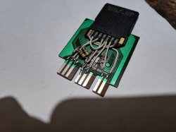
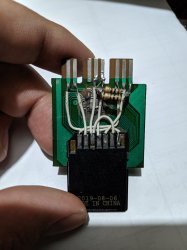
@Varon9 The connections seem correct. (The 100||100 ohm R couldn't be the reason either (I use 47 on mine - in fact FAT PS2 need lower values in general.))
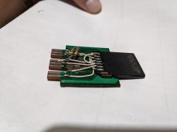
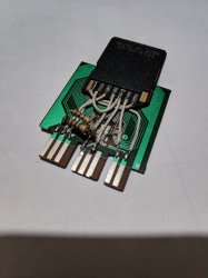
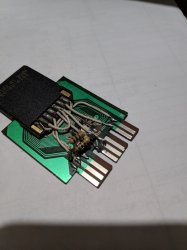
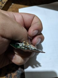
Do you have a multimeter or some sort of continuity tester? If so, (with the MC-SDCard disconnected from the PS2) check each two lines for short circuit (those that are close together. It is very possible that when soldering you overheated the SDCard and melted the pads so they touched internally for example. Or you connected them externally, but it isn't easily visible. It is always a good idea when doing such thing to first check that, as it is very common to make mistakes (I know from experience

).
Also in general, when you test on multiple things, (like in this case you tested on two ports), you should have started with port 2 and when you saw it wasn't working, tried with a known-working PS2 MC, to know if the port still works or not.
BTW, if you are using FreeMCBoot or some other MC-exploit to load stuff, now that both ports are damaged, that won't work too...
Also - how did you disable the original MC from responding? You should cut the /CS (/SS) line and connect the one of the MC chip to the Vdd (+3.5V MC pin 5) with a resistor (47ohm again or 100 ohm should work). But this shouldn't have damaged the PS2 AFAIK... (unless the cards have some odd modes...). So no need to look into that until you determine what is wrong with the PS2.
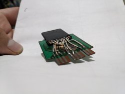
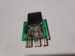
I see solder on pin 3 of the MC. If you ever connected something to that and powered-up the PS2 with it connected, you may have damaged something very seriously, as it is ~7.5V.
As for repairing the PS2, find the service manual that is closest to your model and find the fuse for the MC ports power.
Older (some? FAT) models have some buffer/protection IC mounted on the PCB with the controller and MC ports and that could be the only thing damaged too, but I don't know an easy way of testing it, and even if you determine it is faulty, it a multi-pin some SMD-type case, for which you probably have no means of replacing (or even finding a new one).
So just check the fuse(s) for the MC ports, and if they aren't what / the only thing that got damaged, then there is little chance of repair.
To check that more easily, just check if there is around 3.5V between Vdd (MC pin 5) and GND (MC pin 4).
And be careful not to short something else when measuring.
Also depending on the PS2 model, you should be ver careful in case you go near the power supply, when the unit is powered on (for FAT models) ... best to avoid such work.
 and i don't know where to look at the ps2 to know what's fried
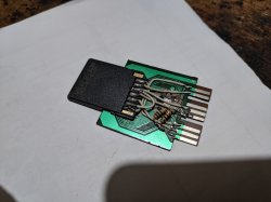

")