PS3 Need a Teensy++ 2.0 alternative to un-brick a CECHA w/ 40nm RSX

devbug_mind

Forum Noob
I'm looking to unbrick a CECHA00 PS3 model with the 40nm RSX that I bricked while converting to official DEX a few months ago for some testing. I have a full NAND flash backup that I made before taking that risk just in case something went wrong.

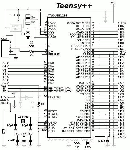
The clip that I had to read/write to the NAND flash went bad at that time and I no longer have the Teensy++ 2.0 either. I was looking to buy a few for backup, but they're out of stock sadly. There are some fake/replicas out there, but I'm not sure if those would work.

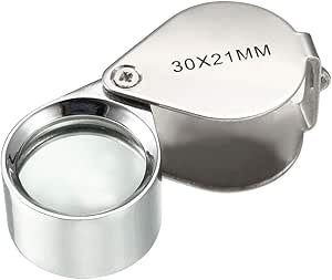
I tried soldering to the NAND flash legs but gave up because of bridges and not having at least a microscope. Since this is a special console model to me, I don't want to take another risk de-soldering the NAND flash. I've looked into the FlashcatUSB XPORT device, but not a lot of info out there if it does works or not.
 
The clones works fine, teensy is made with an standard microcontroller, and the rest of the board circuit is simple
There was some clones with an small problem of voltages (long to explain) but it was not causing any harm

If you still have the damaged clip i would say to try with it or/and try to "fix" the damaged clip pins, maybe you are lucky, at this point it doesnt matters what you write to the flash because you have a valid dump... you could fill the flash with 0xC0CAC01A for fun and restore it later with your valid dump

About soldering wires to the NAND pins.. i would say the microscope is not really required, but a multimeter is a "must have"
The point is... you could do a soldering even if you are not able to see with precission what you are soldering... lets say... like blind soldering. And check with the multimeter if you was lucky
And get also "desolder braid" and flux... thats anoter "must have" to remove the bridges... before starting the job you should assume you are going to make some, but dont get stressed, just remove the bridge with the desoldering braid and start again

Check the last photos of this link also, is a nice trick to prevent bridges http://ultrakeet.com.au/write-ups/kaptonMasking
 
The clones works fine, teensy is made with an standard microcontroller, and the rest of the board circuit is simple
There was some clones with an small problem of voltages (long to explain) but it was not causing any harm
Ohhh, I just thought they weren't safe to use at all after reading in the teensy forum to avoid the clones for whatever or unknown reasons to me : D, but good to know then if they work fine.
If you still have the damaged clip i would say to try with it or/and try to "fix" the damaged clip pins, maybe you are lucky, at this point it doesnt matters what you write to the flash because you have a valid dump... you could fill the flash with 0xC0CAC01A for fun and restore it later with your valid dump
I no longer have the damaged 360 clip. I tried fixing it, especially the pins, but ended up messing it more sadly. I'm glad I was able to make the full NAND flash backup before attempting what I did though.
About soldering wires to the NAND pins.. i would say the microscope is not really required, but a multimeter is a "must have"
The point is... you could do a soldering even if you are not able to see with precission what you are soldering... lets say... like blind soldering. And check with the multimeter if you was lucky
And get also "desolder braid" and flux... thats anoter "must have" to remove the bridges... before starting the job you should assume you are going to make some, but dont get stressed, just remove the bridge with the desoldering braid and start again
I found it a bit hard to do it with no microscope, so I then tried using the camera of a phone to zoom-in, but no third hand and it was kind of blurry from far, and to look better I had to put the phone very close to it, even to see if I had bridges or not. I only managed to solder three cables then stopped after getting bridges soldering the next one.

I've looked into some of the Andonstar microscopes like the AD207 and ADSM302. About the multimeter, I do own one but I wasn't aware of checking bridges with that. Very good to know. Messing with these consoles really got me interested in becoming an electronics technician.
Check the last photos of this link also, is a nice trick to prevent bridges http://ultrakeet.com.au/write-ups/kaptonMasking
Funny that you gave me that link, because that page and that trick alone was the reason why I attempted soldering to the NAND flash legs using that tape, but somehow it always ended up not sticking well after using flux or still ended getting a bridge. I wonder if the soldering iron tip wasn't very good/thin for that and the reason why it caused bridges or the AWG wire that I used (I think it was 28AWG). Maybe I should try with a thin soldering iron tip and 0.05mm 30AWG PTFE wire so it won't break easily.

This clip should have been be the best alternative but it is expensive and I'm surprised there's no affordable clone : D
 
Just to get an idea of how simple is the circuit of the tensy 2.0 board... this is the complete schematic, there are a couple of capacitors resistors a crystal and thats all... and all them are the design suggested in the datasheet of the Atmel AT90USB128 chip
In other words, the chip is standard and the design of the board is standard too, is very easy to clone it
Teensy%2B%2B_2.0_schematic.jpg


I use a jewerly loupe like this one (50x though) a lot to check this small details of electronics, are easy to find, around 3$
I use to check it under a lamp, but there are many times where im not completly sure if i have a bridge, either because what im trying to see is a bit "hidden" by something else, or because there is some shining or light reflection that looks like the pins are connected with each others. Thats when the multimeter comes in handy :encouragement:
You need to setup the multimeter to meassure resistance... if resistance = 0 it means there is no bridge at all (the pins are completly separated)
Anyway... after doing all the solder job you need to check with the multimeter for bridges in all the solders... recheck... and triplecheck just to be sure you are not going to burn something the first time you power it
51dDH0kXg3L.__AC_SX300_SY300_QL70_ML2_.jpg


In the photos of the link keep attention to where he is touching with the solder iron... he doesnt touches the pin directly, he touches at his base, in the circuit board where the pin is soldered... lets say... he only touches the pin at his tip, but the wire is soldered at the top of the pin
But there is no need to touch it, the heat is going to be transfered from the board to the pin all along because are already soldered... and when you are in that state (the pin is hot and ready) you touch the pin with the wire from your other hand... then keep the wire steady and separate the solder iron to allow it to solidify

The point is... touching the pin at his base gives you more precission with the solder iron, it allows to "preheat" only one pin, and the kapton tape protecting the surrounding pins helps the solder to attach only to the hot pin

For this trick to work is important to use KYNAR wire though, in this photo it cant be seen well, but the wire is already "pretinned" (it have an small "bubble" of solder in his tip)
P1020086.JPG

In other words... the tip of the solder is clean (this way there is less probability for the melted solder to spread randomnly)... and the solder is added together with the wire
This also allows you to control very well the amount of solder added to each pin, the minimal is the better

The KYNAR wire have a copper core with a bath of silver... that silver bath allows to "pretin" it easilly like in the photo
 
Last edited:
Back
Top