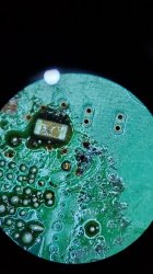
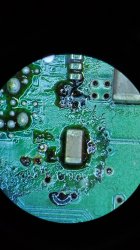
Hey y'all, first time reflowing rsx. I noticed bga has 4 pads on each corner ( not the solder balls) and they've melted fast no longer making contact with the chip. The cell has them too, they kinda look like little pillars holdind the chip. Is that the end for the reflow? What are those things for? Any help greatly appreciated.
You are using an out of date browser. It may not display this or other websites correctly.
You should upgrade or use an alternative browser.
You should upgrade or use an alternative browser.
Reflow question
- Thread starter WendellX
- Start date
sandungas
Developer
Yep, are just dummy pillars to prevent the substrate to "squeeze" the BGA balls
The theory is... they calculated an idealistic distance in between the motherboard surface and the bottom of the CELL/RSX substrate, and that "pillars" have that exact height they calculated. When the BGA balls are melted (in liquid state) the bottom of the CELL/RSX substrate should lay on that 4 "pillars" naturally
This kind of height adjustment depends a lot of the diameter of the BGA balls btw
There is people that removes the 4 pillars though but i like them, i think is a nice idea
vyktormvmpay25
Senior Member
He have same rework station as mine. I may pop in his channel from time to time as Victor Mures (real name).
Those pillars are tiny caps and they are there as spacers. Once alloy is reached liquid stage and boiling under ic it may be possible to merge some of connection. We use 06mm soldering balls, if we manage to get ic close enough to those spacers (03mm caps) then no more bad interconnected/merged balls will happen in that boiling process. [emoji6]
sandungas
Developer
The original pillars are 3mm heigt ?, have you tryed to replace them by something with 4mm height ?, i guess this would prevent (a bit more) the BGA balls to merge with each others in extreme overheating eventsThank you @Computer Booter!
He have same rework station as mine. I may pop in his channel from time to time as Victor Mures (real name).
Those pillars are tiny caps and they are there as spacers. Once alloy is reached liquid stage and boiling under ic it may be possible to merge some of connection. We use 06mm soldering balls, if we manage to get ic close enough to those spacers (03mm caps) then no more bad interconnected/merged balls will happen in that boiling process. [emoji6]
Is going to make the BGA balls more prone to "break" when the pull off from the heatsink though
Basically.. by modifying the height of the pillars we are changing the width of the BGA solder balls
")
_XBrD4shDOE_808_
Member
I have a theory of what can happen with the use of "pillars" taller than the original, I don't know if it makes much sense but here I am.
CPUs further away from the board with the same BGA size, as mentioned, due to the stress of temperature variation, these BGA's may crack, that "extra" height added later may occur, when the solder ball cools down, it should not be able to contract enough and be "pulled" both up and down, leading to a crack at one end of the contact.
@vyktormvmpay25 are these pillars not removed along with the old weld when reballing? in the PS3 reballing videos I had never noticed this detail.
vyktormvmpay25
Senior Member
03mm not 3mm, no I won't modify 04 thereThe original pillars are 3mm heigt ?, have you tryed to replace them by something with 4mm height ?, i guess this would prevent (a bit more) the BGA balls to merge with each others in extreme overheating events
Is going to make the BGA balls more prone to "break" when the pull off from the heatsink though
Basically.. by modifying the height of the pillars we are changing the width of the BGA solder balls
Won't worth much modification from what factory did, if you check in most cases from factory rsx or cell won't touch those.
vyktormvmpay25
Senior Member
I find them on scrap boards only.
sandungas
Developer
You can use any piece of metal with the shape of a cube (or dice), the only requirement is that it needs to be made of metal because is going to be soldered... and also his proportions needs to be very well adjusted
Right now... the most accurate way to do it i figure is by using a copper sheet with 03 thickness and cut it in cubes of 03x03x03. This way there are 2 sides of the cube with the exact meassure (mechanized by the machine that made the copper sheet in a industrial process)
If you ask me to choose in between 2 extreme options (outside of the aceptable ranges) for the shape of that "fat pillar" i would choose to reduce the gap the most posible
You know... if we increase the gap a lot the BGA balls are going to solidify like "thin pillars" and are going to be very fragile
All this depends of the original diameter of the BGA ball of course because his diameter indicates the amount of material
And also it depends of the gap... personally i would try to reduce the gap (vyktor said is 0.3mm so i would try to reduce it to 0.2mm), but also i would try to use balls with a smaller diameter (to reduce the amount of material)... and before the solder solidifyes i would "press" it on top to squeeze the balls the most posible, lol
But this is the kind of experiment i would do in scrap boards only, because i think is a good idea but im not completly sure
You know... when the solder gets fluid everything goes a bit out of control, like trying to control water, you dont know well how is going to move, is the kind of thing we can theorize as much we want, but i think even the professional engineers would need to do some tests in a laboratory with a microscope recording video in HQ to see how the solder ball changes his state in between solid->liquid->solid to understand well where are the limits
Right now... the most accurate way to do it i figure is by using a copper sheet with 03 thickness and cut it in cubes of 03x03x03. This way there are 2 sides of the cube with the exact meassure (mechanized by the machine that made the copper sheet in a industrial process)
When the BGA ball gets solid is not an sphere anymore, is mostly like a "fat pillar" (with a belly at the middle all around)I have a theory of what can happen with the use of "pillars" taller than the original, I don't know if it makes much sense but here I am.
CPUs further away from the board with the same BGA size, as mentioned, due to the stress of temperature variation, these BGA's may crack, that "extra" height added later may occur, when the solder ball cools down, it should not be able to contract enough and be "pulled" both up and down, leading to a crack at one end of the contact.
@vyktormvmpay25 are these pillars not removed along with the old weld when reballing? in the PS3 reballing videos I had never noticed this detail.
If you ask me to choose in between 2 extreme options (outside of the aceptable ranges) for the shape of that "fat pillar" i would choose to reduce the gap the most posible
You know... if we increase the gap a lot the BGA balls are going to solidify like "thin pillars" and are going to be very fragile
All this depends of the original diameter of the BGA ball of course because his diameter indicates the amount of material
And also it depends of the gap... personally i would try to reduce the gap (vyktor said is 0.3mm so i would try to reduce it to 0.2mm), but also i would try to use balls with a smaller diameter (to reduce the amount of material)... and before the solder solidifyes i would "press" it on top to squeeze the balls the most posible, lol
But this is the kind of experiment i would do in scrap boards only, because i think is a good idea but im not completly sure
You know... when the solder gets fluid everything goes a bit out of control, like trying to control water, you dont know well how is going to move, is the kind of thing we can theorize as much we want, but i think even the professional engineers would need to do some tests in a laboratory with a microscope recording video in HQ to see how the solder ball changes his state in between solid->liquid->solid to understand well where are the limits
ElGris
Senior Member
I also didn't notice those "pilars" you're mentioning, but I discovered something..
Those pilars are actually little smd caps, that you can take from a lot of cell phone boards, but the thing that bothers me is that one of them in the pic is in vertical, while the others are in horizontally. I must say this was the first RSX I removed just for testing purposes, and it was so damn heavy that my vaccum pencil loose it lol, so it went over the bgas again. Maybe that's where it got vertically, or maybe not..
The funny thing is seeing Chony using some caps to use them as support for the actual rsx pcb. Isn't it funny?
Btw, ignore the cheap ass flux and all the crap.
Attachments


sandungas
Developer
It was just a coincidence, when you remove the RSX the solder is liquid and his bottom surface is completly wet with flux, so i guess it could "suck" the pillars in up direction...the thing that bothers me is that one of them in the pic is in vertical, while the others are in horizontally.
In other of your photos there is another pillar soldered in a angle (not completly flat), it seems that one was being sucked too, but the solder solidifyed before it was taken into rapture \o/
I really thing that can be replaced by a little copper cube, the SMD components burns (and break at the center), but a cube made 100% of solid copper is going to resists a lot better
sandungas
Developer
And btw... it doesnt really needs to be a perfect cube of 0.3x0.3x0.3 mm
The only meassure we really need to respect from that dimmension it to keep (at least) one side of the cube with 0.3mm but the other sides could have any other, instead of 0.3x0.3x0.3 mm it could be:
0.3x5x0.3 mm <--- a rectangle
5x5x0.3 mm <--- an squarte, but bigger than the original
The point is... in this 2 examples im keeping the original gap of 0.3mm and the other meassures doesnt matters much because there is not any other components in the surroundings, so you can make them bigger
Similar threads
-
 Ps3 fat artifacting and then freezes soon after booting
- Started by khalidhotaki
- Replies: 4
-
-
-
 PS3 2103A – Dropped console, delid, reflow and other
- Started by Cheshire UK
- Replies: 11