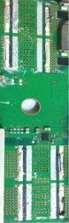
Ah nice work, the scratches are o.k because in those areas it's either all (-) or it's all (+) under the surface. Exactly the same as on top of the surface. See image below (from Sandungas - on Page 103)
The Grey area = Negative (-)
Red & Orange = Positive (+)
View attachment 25916
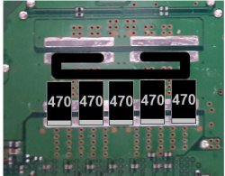
So next... you need to just clean up a little the NEC area where you removed them. Try to remove any black plastic left over from the NECs you removed, but the rest you can leave as it is, because that grey stuff on top of the contact strips, is like a dried solder paste and you can solder on top of that again when you solder new Tantalums on those contact areas. It melts into the rest of the solder.
And those thin layers of metal, sitting (soldered) on the contact strips, can stay there also, because it's all conductive anyway and sometimes trying to remove them can cause accidents on the board, but if you are not new to soldering, etc, then you can try to remove them, it makes no difference, just makes the Tantalums sit slightly higher, like 0.1mm, so it's nothing.
I would suggest, you leave all the original solder from the NECs on the board, and you can re-use that again later for soldering in your Tantalums.
Also, maybe for now, only work on those 4 NECs, and no more, for now. Then you can find out if that burnt NEC was the problem for your PS3, and if that's the case, then maybe the other NECs can stay on the board for now, if they work well.
EDIT: If you also take off the NECs on the RSX & CELL side, you will need to add bridge wire(s) and it's easier to leave those NECs in place, more success stories were done that way. Test and see what you get before taking all of the NECs off.


")
