Could you paste your 'errlog' from the syscon shell - the ps3_uart.py u are using
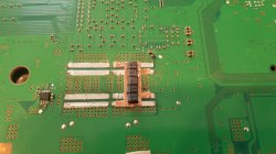
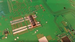
44ohm is not good, 69+ is a working RSX chip.
Here's the log, and a few other things I got out of it
> errlog
errlog
ofst[ 80]:err_code:0xffffffff, clock:0xffffffff
ofst[ 84]:err_code:0xa0403034, clock:0xffffffff
ofst[ 88]:err_code:0xa0403034, clock:0xffffffff
ofst[ 92]:err_code:0xa0403034, clock:0xffffffff
ofst[ 96]:err_code:0xa0403034, clock:0xffffffff
ofst[100]:err_code:0xa0403034, clock:0xffffffff
ofst[104]:err_code:0xa0403034, clock:0xffffffff
ofst[108]:err_code:0xa0403034, clock:0xffffffff
ofst[112]:err_code:0xa0403034, clock:0xffffffff
ofst[116]:err_code:0xa0403034, clock:0xffffffff
ofst[120]:err_code:0xa0403034, clock:0xffffffff
ofst[124]:err_code:0xa0403034, clock:0xffffffff
ofst[ 0]:err_code:0xa0403034, clock:0xffffffff
ofst[ 4]:err_code:0xa0403034, clock:0xffffffff
ofst[ 8]:err_code:0xa0403034, clock:0xffffffff
ofst[ 12]:err_code:0xa0403034, clock:0xffffffff
ofst[ 16]:err_code:0xa0403034, clock:0xffffffff
ofst[ 20]:err_code:0xa0403034, clock:0xffffffff
ofst[ 24]:err_code:0xa0403034, clock:0xffffffff
ofst[ 28]:err_code:0xa0403034, clock:0xffffffff
ofst[ 32]:err_code:0xa0403034, clock:0xffffffff
ofst[ 36]:err_code:0xa0403034, clock:0xffffffff
ofst[ 40]:err_code:0xa0403034, clock:0xffffffff
ofst[ 44]:err_code:0xa0403034, clock:0xffffffff
ofst[ 48]:err_code:0xa0403034, clock:0xffffffff
ofst[ 52]:err_code:0xa0403034, clock:0xffffffff
ofst[ 56]:err_code:0xa0403034, clock:0xffffffff
ofst[ 60]:err_code:0xa0403034, clock:0xffffffff
ofst[ 64]:err_code:0xa0403034, clock:0xffffffff
ofst[ 68]:err_code:0xa0403034, clock:0xffffffff
ofst[ 72]:err_code:0xa0403034, clock:0xffffffff
ofst[ 76]:err_code:0xa0403034, clock:0xffffffff
> bestat
bestat
(Error State) (Unknown Error)
> powerstate
powerstate
ATA Power : OFF
PCI Power : OFF
RSX Power : OFF
XDR Power : OFF
Eurus Power : OFF
SB Power : OFF
RSX Thermal Sensor : UNAVAILABLE
BE Thermal Sensor : UNAVAILABLE
> disp_err
disp_err
CheckStop: None
PLLUnlock: 0
RSX Int: None
PowerSeq: 00


")

