chugAlugDonna
Forum Noob
-Chumdiddy1, good to hear your enthusiasm for achieving boot! I hope to join you soon, mine's been in a box in parts for over a decade, I think it's still on ofw3.40!
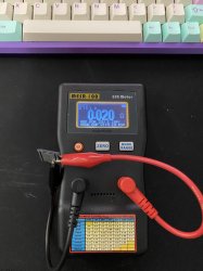
I forgot to mention the pictures and cap and resistance measurements from above are for my CECHH machine...Haven't worked on my launch model yet...
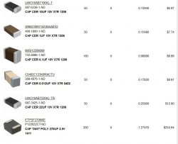
-RIP-Felix, the more I read and research I agree with you about the caps Workz_777 used in his NEC/TOKIN recreations. I think his problem wasn't ultimate capacitance, but ESR. I agree the caps he used must've been a much higher ESR than recommended for using 16 per chip. I only realized this after finally ordering my caps today. I couldn't find any 470uF caps with anywhere near as low as ESR as the 270uF ones you used. I also couldn't find ANY .01uF ceramic caps in the 1206 size and 10v, ended up getting .012uF caps in a much smaller size...Also wanted to ask him about using all 10v ceramic caps in his mix with the 2.5v tantalums. Still hoping he'll chime in soon. As far as the temp of my hakko iron, I'll have to double check...All I know is that I was using a higher temp than I would normally have to use, aka, one for soldering SMC's with ROHS solder. A higher temp. than I like...I ordered my caps from DIGIKEY, and the weird thing was that when filtering down the results for tantalum polymer caps, those Panasonics NEVER showed up under ANY circumstances. I had to search for the specific part number you provided, and there they were. AND, when I did search for them they showed up, but almost triple the cost and much lower availability. I freaked out and started looking at other sites, and when I came back to DIGIKEY, the availability was back up, the price was back down...WTF?? I had an OH $HIT moment of demand exploding for these...SO I ordered enough ceramics and tantalums to experiment with...but at a cost obviously. You gotta pay to play, right??
I forgot to mention the pictures and cap and resistance measurements from above are for my CECHH machine...Haven't worked on my launch model yet...
-RIP-Felix, the more I read and research I agree with you about the caps Workz_777 used in his NEC/TOKIN recreations. I think his problem wasn't ultimate capacitance, but ESR. I agree the caps he used must've been a much higher ESR than recommended for using 16 per chip. I only realized this after finally ordering my caps today. I couldn't find any 470uF caps with anywhere near as low as ESR as the 270uF ones you used. I also couldn't find ANY .01uF ceramic caps in the 1206 size and 10v, ended up getting .012uF caps in a much smaller size...Also wanted to ask him about using all 10v ceramic caps in his mix with the 2.5v tantalums. Still hoping he'll chime in soon. As far as the temp of my hakko iron, I'll have to double check...All I know is that I was using a higher temp than I would normally have to use, aka, one for soldering SMC's with ROHS solder. A higher temp. than I like...I ordered my caps from DIGIKEY, and the weird thing was that when filtering down the results for tantalum polymer caps, those Panasonics NEVER showed up under ANY circumstances. I had to search for the specific part number you provided, and there they were. AND, when I did search for them they showed up, but almost triple the cost and much lower availability. I freaked out and started looking at other sites, and when I came back to DIGIKEY, the availability was back up, the price was back down...WTF?? I had an OH $HIT moment of demand exploding for these...SO I ordered enough ceramics and tantalums to experiment with...but at a cost obviously. You gotta pay to play, right??