chugAlugDonna
Forum Noob
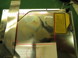
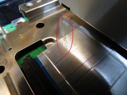
Finally got me caps in the mail. Had time to get started tonight with the CECHH machine from my prev. post. First experiment is to try strictly the tantalums to replace the four nec's i removed from it's backside. I started with 12 per chip, still had a fast YLOD and didn't boot. Tried adding four more just for the heck of it for 16 per chip. Still has YLOD, but I swear it remains green for at least a second longer than it did before. Might be wishful thinking, I hope not. The original nec's are still in place on the chip side of the board(if you haven't been following). Resistance measurements are still like they were in my prev. post, I still get one higher cap reading over the one group of the cell when measuring hot rail to hot rail. This one ~much~ higher reading might mean a problem with one of the caps underneath on the cell side?? I don't understand the electrical side much, more of a mechanical guy...Anyway, the surgery went alright I think. NOT an easy job, I really wish my caps had longer legs sticking out the sides like some do, but the cathode? one is nearly flush with the cap body, and makes visible confirmation of a good joint almost impossible. These appear to be meant for hot air install, but I'm hot air-phobic and used only my iron with large bevel tip at 700F. I had pre-tinned the contacts underneath and added some solder to my clean rails as well. Then soldered each side one at a time while pushing down on body of cap to finally sit flat on board. When reassembling for test, I noticed the underside of my BD drive shows signs of some heat discoloration, on the ribbon as well. I also noticed some possible damage to the ribbon cable in two spots I hadn't noticed before. Can someone tell me the bare minimum to reassemble for a test to see if YLOD went away? Does hdd have to be connected? Does BD drive have to be connected? I would think so if either of these being bad can be a cause of YLOD as previously mentioned? What about usb port board, or wireless thingy?
 ) the remaining NECs, that could be another way to find if the console is able to boot with the actual fix.
 ")