Didn't know about the voltage, got these caps as they were on ebay listed as ps3 repair capacitors when I was looking for 470uf caps. What ones would you recommend and do you know a place to buy that lets you buy small lots without charging hundreds ontop. I had trouble with actual component websites when looking which is why I went to ebay in the first placeOkay, finally read your originl issue. Sounds like random freezing. Did it occur only in PS2 games? Or did it happen in PS3 also? And does the console still boot, or are you getting a YLOD on boot now. If so, how long does it take before it happens (from power button press to beeps)?
So, this wording is misleading. It sounds like you are saying bad nec tokins can be "healed" by heat. That idea has been proven false. Any console that boots after "heating up" is related to the BGA/Bumps.
At this point tho, it's pointless to use these type of indicators to diagnose. We have the SYSCON for diagnosis now, we don't need to revert back to the dark ages before the error codes. That type of observation is useful to build corroborating evidence, but we shouldn't rely on it.
Yeah, you gotta pay attention to polarity.
I don't wish to throw shade on your accomplishment, but those caps are rated for 6v. That's fine, they'll work just fine under normal operation. However, if the VRM short, the 2.5v caps would see 4-5v applied and act as a fuse, preventing the RSX from burning it out. 6v caps will allow the short voltage to reach the RSX. So 2.5v caps are recommended for an added layer of voltage protection.
You are using an out of date browser. It may not display this or other websites correctly.
You should upgrade or use an alternative browser.
You should upgrade or use an alternative browser.
PS3 (Research/Experimental) - NEC/TOKIN Capacitors Replacement - YLOD
- Thread starter Naked_Snake1995
- Start date
RIP-Felix
Senior Member
... What ones would you recommend ...
PS3 Tantalizer - Beta Release (v0.3b)Notes:
(Order or Download from OSH Park HERE)
Pictures:
- If you choose to use this PCB, you are doing so at your own risk! I cannot be held responsible for any damages or loss of life resulting from use of this product!
- This PCB is designed to make it easier and safer to attach tantalum/MLCC capacitors to your PS3. Removing the NEC/TOKINs and replacing with Tantalum/MLCC capacitors is an experimental mod not guaranteed to fix the problems you are experiencing. You must properly troubleshoot your console to decide if this mod is right for you.
- You must order a minimum of 3 boards. I recommend ordering 3x (9 Tantalizer boards cost $4.05). That will be enough to replace all the NEC/TOKINs on a PS3 and give you a spare in case there is a defect in the other 8.
- MLCC pads are meant for 0805 case size.
- Tantalum pads are for 7.3 x 4.3 x 1.9mm (LxWxH). You can use other types of capacitors that fit this footprint, such as aluminum polymer, tantalum polymer, etc. However, they must be low ESR/ESL processor decoupling capacitors. The PCB takes up 0.8mm of height, so caps need to be low profile (less than 2mm). Each one should be less than 9mΩ ESR, 4.5mΩ ideally. I recommend...
- You do not need to buy the MLCC capacitors. The 470uF capacitors are enough on their own. However, the MLCC capacitors help to attenuate the higher frequency noise component up to around 2MHz, better mimicking the NEC/TOKIN proadlizer it's meant to replace. This is probably overkill on PS3's with 1000uF tokins. I still recommend using 470uF caps, because 3x 330uF is only 990uF and may not be enough. It's better to have more capacitance than less, but not too much more. The MLCCs are more needed on 90nm CPU/GPU early models (A-H). They have noisier switching VRM and higher load, which requires more decoupling than later models. Use them if your tokins are OE128 models. You probably don't need them otherwise.
- You must choose 0.8mm board thickness in the options during checkout. This ensures it'll fit underneath the RF shield when you reassemble the console. It also has double thick copper planes for high power applications such as this.
- You must buy 1.9mm height capacitors or smaller. This ensures it'll fit underneath the RF shield when you reassemble the console.
- You can download the Gerber files from OSH Park if you perfer to have another board house manufacture your Tantalizers. Just be sure they know the edges are castellated and that you need 0.8mm board thickness.
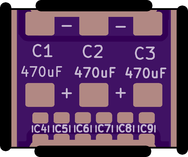
Note: The following pictures are of v0.3a I made with 7x MLCC pads. I decided to remove C10 because there was too little clearance between +/GND. v0.3b linked above will not have 7 MLCC pads. It has 6, but is otherwise identical to the pictures below.
View attachment 35177 View attachment 35178
View attachment 35179 View attachment 35180
Discussion:
I received the alpha revision and it looks good, except that the MLCCs are too close to the positive rail for comfort IMO. SO I have revised it to only have 6 pads. I am confident there is enough room now. I got the castellated edges right this time and they wick the solder really easily along the entire edge of the slot.
I have not attempted to use them yet, so they are untested on console. The next step is to populate and test. I have opened the beta, so anyone can DL or order them from OSH Park. But you should know they are untested.
Unlike the last beta, these came from the factory pretty well finished. I didn't need to trim them much. A castellated slot proved to be much better.
It's fine if you don't want to participate in the beta, potentially burning down your house or damaging your PS3. Once others and I have installed it and confirmed they work, I'll update the listing on OSH park with the v1.0 monker, indicating a fully tested/working PCB.
olokos
Member
Thank you guys for your replies!
The freezing I was talking about in my other posts was only related to a particular game - Stuart Little 3: BIg Photo Adventure which is a PS2 game.
Apart from that single title, I have played multiple hours on the PS3 already.
PS1 Games ran perfectly fine (007 tomorrow never dies runs perfectly)
PS2 Games ran perfectly fine (NFS Series, Tekken 5 - no issues in those games, just SL3, that's why I was trying to get a patch for it)
PS3 Games ran perfectly fine aswell.
My PS3 was mostly maxing out at 70-75*C, usually hovering 65-67*C, I never had any freezing issues in general, everything ran perfectly including playing PSX,PS2,PS3 games using original discs in the drive aswell as playing dumps.
I haven't played on this PS3 in a month or two at all, I recently tried it again, tried to play SL3 (which has freezing issues on PS3 by itself) and after a few attempts of the game freezing I exited out of the game by holding PS3 button on controller and just went back to the main menu of XMB, switched over the display to my PC and just left it idle.
I have left the console idle for a few days (temps were fine) as I was installing games and that took massive amounts of time.
I'm not to worried about my progess, saves and data at all, as soon as I felt comfortable with 4.88 Evilnat I dumped everything that is possible to dump via XMB, so I also dumped the EID root key, so that can be recovered no problem, I think.
I just hope to get this specfic console back to life, because well, it really is an awesome piece of hardware and I don't think buying another one and having the same issue is the best way.
So yeah there are 2 separate issues, not really related:
This is how it goes right now:
Connect power -> red solid light (normal) -> press power button -> green -> yellow -> blinking red
Can't wait to get the JTAG to see what the PS3 says the problem is.
BTW. Previous owners delidded 1 or 2 chips, but seems like it was done right as there was still good thermal paste, but I replaced both sides of IHS with my own thermal paste and the IHSs are still there as designed.
The freezing I was talking about in my other posts was only related to a particular game - Stuart Little 3: BIg Photo Adventure which is a PS2 game.
Apart from that single title, I have played multiple hours on the PS3 already.
PS1 Games ran perfectly fine (007 tomorrow never dies runs perfectly)
PS2 Games ran perfectly fine (NFS Series, Tekken 5 - no issues in those games, just SL3, that's why I was trying to get a patch for it)
PS3 Games ran perfectly fine aswell.
My PS3 was mostly maxing out at 70-75*C, usually hovering 65-67*C, I never had any freezing issues in general, everything ran perfectly including playing PSX,PS2,PS3 games using original discs in the drive aswell as playing dumps.
I haven't played on this PS3 in a month or two at all, I recently tried it again, tried to play SL3 (which has freezing issues on PS3 by itself) and after a few attempts of the game freezing I exited out of the game by holding PS3 button on controller and just went back to the main menu of XMB, switched over the display to my PC and just left it idle.
I have left the console idle for a few days (temps were fine) as I was installing games and that took massive amounts of time.
I'm not to worried about my progess, saves and data at all, as soon as I felt comfortable with 4.88 Evilnat I dumped everything that is possible to dump via XMB, so I also dumped the EID root key, so that can be recovered no problem, I think.
I just hope to get this specfic console back to life, because well, it really is an awesome piece of hardware and I don't think buying another one and having the same issue is the best way.
So yeah there are 2 separate issues, not really related:
- PS2 Game stuart little locking up itself (but not console at all) when loading into the game world (new game or loading a save)
- My PS3 just died recently
This is how it goes right now:
Connect power -> red solid light (normal) -> press power button -> green -> yellow -> blinking red
Can't wait to get the JTAG to see what the PS3 says the problem is.
BTW. Previous owners delidded 1 or 2 chips, but seems like it was done right as there was still good thermal paste, but I replaced both sides of IHS with my own thermal paste and the IHSs are still there as designed.
sandungas
Developer
Ok, let me rewrite it in a different way with an exampleSo, this wording is misleading. It sounds like you are saying bad nec tokins can be "healed" by heat. That idea has been proven false. Any console that boots after "heating up" is related to the BGA/Bumps.
At this point tho, it's pointless to use these type of indicators to diagnose. We have the SYSCON for diagnosis now, we don't need to revert back to the dark ages before the error codes. That type of observation is useful to build corroborating evidence, but we shouldn't rely on it.
All the capacitors are rated to work under normal condition in a specific range of temperatures... just to throw some numbers, lets say the range is 10ºC up to 90ºC
But when the capacitor wears out the range changes... lets say 30ºC up to 75ºC
I have choosen the value 30ºC for this example intentionally because it could be close to the room ambient temperature
Lets say... if the room is at 28ºC, the first time you press the power button the device is not going to work because his temperaure is out of the range, but this attempt to boot heats a bit the capacitor (lets say 1ºC more)... so now we have the capacitor at 29ºC (and the range at 30ºC-75ºC)
The next time you press the power button the capacitor temperature increases another 1ºC more... and the device boots because you entered in the range
I also mentioned the capacitors inside the PSU because this is a general effect, it happens with all kind of capacitors
Im not telling that the heat can fix them permanently, im just telling the heat can help them work temporally (enought to boot the device in a very unestable state) in some special cases (when the device refuses to boot at the first attempts but boots at the next attempts)
RIP-Felix
Senior Member
Working through my spreadsheet of error codes and correlating errors. Came across this and wanted to let you know...Another set of logs from another console.
ERR 00: 00000000 A0213013 FFFFFFFF
ERR 01: 00000000 A0202120 FFFFFFFF
ERR 02: 00000000 A0202120 FFFFFFFF
ERR 03: 00000000 A0202120 FFFFFFFF
ERR 04: 00000000 A0202120 FFFFFFFF
ERR 05: 00000000 A0202120 FFFFFFFF
ERR 06: 00000000 A0202120 FFFFFFFF
ERR 07: 00000000 A0202120 FFFFFFFF
ERR 08: 00000000 A0202120 FFFFFFFF
ERR 09: 00000000 A0202120 FFFFFFFF
ERR 10: 00000000 A0202120 FFFFFFFF
ERR 11: 00000000 A0202120 FFFFFFFF
ERR 12: 00000000 A0202120 FFFFFFFF
ERR 13: 00000000 A0202120 FFFFFFFF
ERR 14: 00000000 A0202120 FFFFFFFF
ERR 15: 00000000 A0202120 FFFFFFFF
ERR 16: 00000000 A0213013 FFFFFFFF
ERR 17: 00000000 A0202120 FFFFFFFF
ERR 18: 00000000 A0202120 FFFFFFFF
ERR 19: 00000000 A0202120 FFFFFFFF
On page 25 of the SYSCON thread @ patricksouza472 fixed A0202120/A0213013 replacing F6302 and C6320. Note, this console produced 10x 2120 to every 1x 3013. @Aran3a noted the same thing on page 45, but we never thought to try these SMDs. @moptop219 on page 218 of the tokins thread noted the same. There's a good chance this is what's wrong with these consoles.
RIP-Felix
Senior Member
Could you post your errorlog and give us your PS3 model?Okay I figured out how to get bringup working. This is the result.
>$ bringup
00000000
# [SSM] Bringup Start.
# [SSM] PS0 ok.
>$ shutdown
00000000
# [PowSeq] Error:A104
# [SSM] PS1 ng.
# [SSM] Cond/Fatal received, msg=24D0.
# [SSM] Fataldown Start.
# [SSM] Fataldown ok.
# (PowerOff State) (Fatal)
NG E00000E0
# [SSM] Clearfatal Start.
# [SSM] Clearfatal ok.
# (PowerOff State)
I'm trying to work out what 3010 is. Not many reports to go off of and yours may help.

RIP-Felix
Senior Member
No, you must not brigde any of them. They can reman unpopulated, no harm, but bridging them is the same as shorting +/GND rails. Will result in 3003 or 3004 error.I have just received the tantalizer 0.3b after placing an order 3 months agoto oshpark.
I intend to populate C1, C2 & C3 only, is it required to bridge any of the pads left empty?
View attachment 35871
Those pads are simply there for you to add MLCC array if you desire/need to attenuate HF noise.
sandungas
Developer
Btw, i guess you already know, but for others curiosity sake... in the PS3 slims and superslims without the NEC/TOKINS sony did pretty much the same than you did in your tantalizer boardThose pads are simply there for you to add MLCC array if you desire/need to attenuate HF noise.
I never took the care to check it with a multimeter and there is no service manual to figure it just by taking a look at it but in the official design there is always a few tantalum caps + a few tiny caps all around
I bet the tiny caps all around are intended for the same purpose than yours, are filtering different frequencies, i been wondering if you was inspired by sony

The only doubt left is to see exactly what they did in that capacitor array for the slims and superslims because maybe it can be copyed accuratelly
In some way you are cloning it, the principle seems to be the same, i guess the only difference is the power requirements
Last edited:
RIP-Felix
Senior Member
Yes!Btw, i guess you already know, but for others curiosity sake... in the PS3 slims and superslims without the NEC/TOKINS sony did pretty much the same than you did in your tantalizer board
I never took the care to check it with a multimeter and there is no service manual to figure it just by taking a look at it but in the official design there is always a few tantalum caps + a few tiny caps all around
I bet the tiny caps all around are intended for the same purpose than yours, are filtering different frequencies, i been wondering if you was inspired by sony
The only doubt left is to see exactly what they did in that capacitor array for the slims and superslims because maybe it can be copyed accuratelly
In some way you are cloning it, the principle seems to be the same, i guess the only difference is the power requirements
I noticed them in later models with TaPol and AlPol caps and wondered why they were needed. The reason I hypothesize is because the NEC/TOKINs proadlizers were better capacitors. They attenuate HF noise frquencies better than TaPol/AlPol do. So I copied their approach to mitigating the loss of this HF noise range with MLCC pads. @vyktormvmpay25 measured the capacitance of those MLCC's at 20uF. I have since recommended various combinations of MLCC's to "theoretically" attenuate the noise better. However, I have not tested their effectivness in the real world. So it's experimental.
The MLCC's don't appear to be needed if you populate all 3 TaPol pads though. The added capacitance appears to make up the difference and then some. And it doesn't seem to negativly affect current sensing or the voltage feedback network, if you use sufficiently low ESR caps (less than 9mOhms each).
Hi there guys,
This is probably not the right thread to post this but I have a question.
I have acquired two working (and in fairly good condition) CECHC03 PS3's. As this is the 4th and 5th times of having a running, working PS3, I would like to keep them that way. Can you fellers recommend some ways to keep them in working condition please? To help delay YLOD?
olokos
Member
Easy mode:Hi there guys,
This is probably not the right thread to post this but I have a question.
I have acquired two working (and in fairly good condition) CECHC03 PS3's. As this is the 4th and 5th times of having a running, working PS3, I would like to keep them that way. Can you fellers recommend some ways to keep them in working condition please? To help delay YLOD?
DELID + Replace thermal paste + Replace thermal pads
Hard mode:
Replace NEC/TOKIN capacitors with thantalium capacitors
Ultra-hard mode (u prolly want a pro to do it for you):
Reball the CPU+GPU, use pro machine to get the CPU GPU off, place new solder balls, use pro machine for solder balls to melt. Nearly impossible to do without professional tools and equipment.
------------------------------------------------------------------------------------------------------------
Back to my issue of a dead YLOD CECHC04.
I tried following this guide:
https://www.psx-place.com/threads/r...s-replacement-ylod.25260/page-192#post-295119
Finally I've managed to disassemble the board and solder the wires exactly as shown here:
https://www.psdevwiki.com/ps3/images/c/cf/COK-001_SC_UART_testpads.jpg
Then I hooked them up to this USB to TTL device:
(huge image so I won't make it an image but a link)
https://a.allegroimg.com/original/112af0/dd0761a04250b962a2b78497e49f
I did download all pip packages and I was using Python 3.10.2
B
USB is on 3V3 mode with a jumper.
I did remove the jumper from the RXD/TXD pins (so I can plug the wires coming from PS3 into the USB, obviously has to be done)
I did connect SC_Rx and SC_Tx to the RXD and TXD plugs on the USB
Then I tried:
python ps3_syscon_uart_script.py COM5 CXR (which is a valid COM port in device manager)
and each time I did get console with a $ sign
sadly, each attempt to write AUTH or auth results in response FFFFFFF
Then I've tried to slap on the PS3 PSU to make sure it's in standby, even connecting the front panel to see the RED LED of standby.
I did put a towel between the PSU and PS3 board, so it's insulated and not shorting anything.
Same thing sadly, auth or AUTH results in response FFFFFF
Am I doing something wrong? I can't really get past the AUTH/auth step.
I've tried with PS3 completely not powered and with PS3 in standby, reopening CMD again and again to retry as mentioned in the guide, but it seems to change absolutely nothing.
I've seen that the TX/RX wires might be reversed. They were correct, but I tried anyway and that also did drop me to the $ prompt, I tried auth and AUTH again with multiple CMD launches separately, but still response FFFF.
I also tried GND + TX + RX wires to USB aswell as reverse TX/RX + GND but same FFFF error.
I can't seem to get past AUTH/auth, either way I tried ERRLOG and the full 32 lines ERRLOG but that also results in FFFF response. :/
I currently have the PS3 disassembled with wires soldered to it. I'd be very happy if somebody could tell me if I'm doing something wrong?
What else should I try?
Last edited:
Easy mode:
DELID + Replace thermal paste + Replace thermal pads
Hard mode:
Replace NEC/TOKIN capacitors with thantalium capacitors
Ultra-hard mode (u prolly want a pro to do it for you):
Reball the CPU+GPU, use pro machine to get the CPU GPU off, place new solder balls, use pro machine for solder balls to melt. Nearly impossible to do without professional tools and equipment.
Brilliant
Thank you for your reply
olokos
Member
No problem, but do slap that like button instead of "thank you" posts.Brilliant
Thank you for your reply
I mean it's nice to read it, but clutters the thread and doesn't make my "Likes received" go up :P
Hey guys pls i need some help and advice, i recently wanted to start up my PS3 CECHG04 40GB model after 7 years of being switch off, i started the console it showed a green light --> yellow --> blinking red then i researched and found this forum i orderd the tantalums from aliexpress then i went on to remove the first pair of NEC/TOKIN on the back, the ones on the right
 to be exact the PS3 started up when to the home screen then the fans increased in speed and a warning message on the top right corner about the CPU overheating after few sec it turned of with a red blinking right so i ordred new thermal paste in the mean time i thought maybe i should remove the other pair of NEC for the GPU in the process i ripped a chunk of the negative side
https://www.dropbox.com/s/8tcefhfuaffplgs/IMG_4683.jpg?dl=0 on the board but the positive sides are still intact, when i added the tantalums the PS3 would show green and immediatly red then blinking red here are some pictures
to be exact the PS3 started up when to the home screen then the fans increased in speed and a warning message on the top right corner about the CPU overheating after few sec it turned of with a red blinking right so i ordred new thermal paste in the mean time i thought maybe i should remove the other pair of NEC for the GPU in the process i ripped a chunk of the negative side
https://www.dropbox.com/s/8tcefhfuaffplgs/IMG_4683.jpg?dl=0 on the board but the positive sides are still intact, when i added the tantalums the PS3 would show green and immediatly red then blinking red here are some pictures


https://www.dropbox.com/s/jee7cazk5zloc83/IMG_4686.JPG?dl=0
https://www.dropbox.com/s/ebbjrhwb9c5ll03/IMG_4689 2.JPG?dl=0
https://www.dropbox.com/s/jee7cazk5zloc83/IMG_4686.JPG?dl=0
https://www.dropbox.com/s/ebbjrhwb9c5ll03/IMG_4689 2.JPG?dl=0
Last edited:
Hi guy wondering if anyone can help. I've just replaced one of the nec/tokin capacitors like the tutorial for 4x 470uf 6v tantalum capacitors and I've gone from yellow flashing light on start up to 3 beeps and flashing red light on start up. Does anyone have i idea of what might be wrong? Thanks in advance. Dan
its a CECHC03 model btw
its a CECHC03 model btw
Easy mode:
DELID + Replace thermal paste + Replace thermal pads
I have 1.5mm artic thermal pads. Will these suffice or should I get 2.0mm pads? Will I need to replace CPU IHS adhesive? If not should I clean away all the old adhesive anyway?
olokos
Member
I have 1.5mm artic thermal pads. Will these suffice or should I get 2.0mm pads? Will I need to replace CPU IHS adhesive? If not should I clean away all the old adhesive anyway?
From what I've read online 1.5mm are the exact size needed for CEHC models. I've ordered 1.5mm ones aswell, but I won't be replacing them until I get my PS3 alive again, so if you do that, let me know if the 1.5mm ones were perfect size or if some chips needed thicker ones. (You can always put back the old thermal pads, if you carefully removed them without damaging them.
I wouldn't replace adhesive at all, of course you have to replace the thermal paste.
Thermal paste goes bad / loses a lot of performance after ~2 years, so you would have to delid again to replace it, needlessly risking damaging the PS3.
Clean the adhesive sure, but only using no force at all or minimal force.
If you can't get it off using your fingernails then just leave it.
I didn't delid my PS3 myself, but as long as the old adhesive doesn't go over dies(rainbowy middle parts of the CPU/GPU) where thermal paste should be and doesn't cause the IHS to be wobbly or causes other mechanical issues, then just leave it.
If the old adhesive doesn't affect thermals or how it's being put back together, I wouldn't touch it at all, unless some old adhesive parts are loose and you can get it off with your fingers. There's too high risk of damaging the board/contacts/components for what it's worth. At best you get a pretty looking inside, at worst you can damage the console.
From what I've read online 1.5mm are the exact size needed for CEHC models. I've ordered 1.5mm ones aswell, but I won't be replacing them until I get my PS3 alive again, so if you do that, let me know if the 1.5mm ones were perfect size or if some chips needed thicker ones. (You can always put back the old thermal pads, if you carefully removed them without damaging them.
I did use 1.5mm for my last PS3 (which got the YLOD about 2 weeks go), and they worked pretty good… problem was the console was already overheating when I got it (the multi stage fan ramp up). In my pre research ignorant state, I cleaned it out and did the 'one size fits all' thermal paste and pads replacement thinking that was a job well done. It ran smoothly, albeit with a consistently loud fan when on. I think I may have brought the YLOD closer with some heavy handed heatsink fan removal as it was welded on. It had been previously opened before I purchased it too.
Hello, wondering if anyone can help. I have a CECHG01, bought it back in 2017 already modified lasted about a year. Never changed the thermal paste so I'm guessing it overheated. When I turn it on it beeps and the red light immediately goes away and there's no light, no blinking red, no yellow, no green. I've tried heating up the RSX and replaced the thermal paste no luck, so I've been researching these forums and everything point towards a YLOD but I have no clue and wondering what it is before I try replacing the NEC TOKIN.
Similar threads
-
 PS3 Interesting PS3 Errors (1802, 1701, 1601) and Capacitor Replacement
- Started by Cheshire UK
- Replies: 2
-
PS3 CECHA00 with several SYSCON errors (3004, 1001,1002, 2120,3011)
- Started by LSL
- Replies: 7
-
PS3 A0801002 after 4 nec/tokin replacement (maybe Felix or anyone help me)
- Started by Swhalegod
- Replies: 3
-
Hello newcomer to the ps3 modding scene, needing help with syscon diagnostic
- Started by ascendantprime
- Replies: 1