PS3 Frankenstein PHAT PS3: CECHA with 40nm RSX

If you have it jailbroken you could just start the ISO.

Otherwise, you can just reposition the BD over where the PSU is. I made a 5v extender and use banana plug-->aligator clip for 12v. This way I can work on the board unimpeeded by the PSU.
20220906_113636.jpg


BTW: I work on the board in this orientation because this is how it's presented in the service manual and schematics.
 
Yeh, but that 2.66V is beyond the max voltage accepted by rdram, i tried replacing the regulator (ic6607), but nothing changed, im getting 2.67 volts there.

The datasheet for rdram says the max is 2.5 +/- 0.13, also the datasheet for the regulator says min/max of 2.45 to 2.55, all the other voltages are correct.

Also the service manual says RSX_FBVDDQ is 1.8v, im getting 2v .

EE+GS do share data lines with RSX, so im keeping that on my head.

Anyway im trying to figure out this voltage differences before trying to continue.
I cant help much with RSX, to be honest i never dedicated much time to understand how it works, neither EEGS
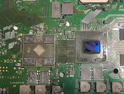
Is just there has been some talks in wiki latelly related with the PS2 "netemu" software emulator that are indirectly related with the PS2 bridge chip (we dont understand well whats its function). And for me this chip was always a mistery so i decided to make the pinout table in wiki, this is when i realized it have 8 pads named "SW" that are related with the EEGS and RDRAM power lines

The reason why this surprised me a bit is because usually most/all power lines are switched directly (or indirectly) by syscon, but in this case it looks like the PS2 bridge is switching the power lines of EEGS and RDRAM, so if we had to draw a graphic of the hierarchy it seems the PS2 bridge is the boss of EEGS
I think this detail is very important for troubleshooting because it would mean that any problem in the PS2 bridge is going to keep one or more of the EEGS subcircuits unpowered

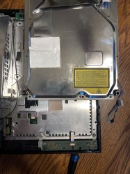
I didn't include the PS2 subsystem's power on that flowchart. I do have one in which I colored in those areas, but the test pads are all on Side B anyway. People are used to looking at the side of the boad with the chips, but SONY designed it to be tested with flying probs on side B. Which works better anyway because we can leave the fan on. I have a testpad location chart here.
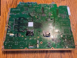
I was looking at your image yesterday trying to figure how to draw that lines and it seems are going to fit fine :)
If you make another version of the image please keep the same exact size in pixels and replace it in wiki in its page where it tells "upload a new version of this file"

Btw, im not completly sure if the PS2 bridge is either switching the mitsumis responsibles to generate the power lines of EEGS and RDRAM... or if is just monitoring that ON/OFF line of the mitsumis

My confussion is because if you take a look at the service manual, all the PS2 bridge pads named "SW" are labeled with an "arrow in" (indicating that are PS2 bridge inputs), and are connected to the voltage regulators (the mitsumis)
But in the voltage regulators (mitsumis) are also labeled with "arrow in" (indicating that are the control signals that switches them)
So... if we trust the arows of the schematics... who the hell is sending the "output" signals in that lines ?
At this point i think the "arrows in" of the SW pads of the PS2 bridge are a mistake in the service manual (are outputs, not inputs), what do you guys think ?

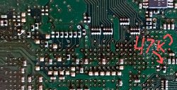
Looking on the schematics page 27 ic 7001 pin 13 is tapped to EE enable(w1) and GS enable (w2), but also tapped to the ground, that's too complex of a circuit for my hobbiest electronics xd
Yeah, following the lines of EEGS pads W1 (EEenable) and W2 (GSenable) to bottom direction are tied to GND
I guess this simply means sony had some prototypes where they was controlling them separatedly by another component, but in retail production they keep them permanently connected to GND (always enabled), i guess in some kind of "idle mode" by default to reduce power consumption

Edit:
Or is a design detail inherited from PS2, just because in some revisions of the PS2 motherboard the "EEenable" and "GSenable" signals was controlled separatedly
Anyway... it doesnt have any importance, are not related with IC7001
 
Last edited:
Ok, yesterday i replaced both rdram and nothing changed.

Today i opened the 2nd console and it had the exact same 2.67v on rdram and 2v on RSX_FBVDDQ, so i considered this normal.

So i jumped into reflowing EE + GS on the 2nd unit, and the ps2 logo came up. I didn't stress test or anything yet, i just saw the ps2 logo, game booting.

I have like 4 donor boards here, so today i bought 0.76mm balls, i will wait them to come next week and replace the first unit EE+GS and probably the 2nd unit too then i let you know here, if both worked.
 
Hello everyone! im glad the forum is up and running again! while the site was down i had received a CECHA00 from japan, upon some analysis i found that this A00 has a 40nm RSX from Sony just like OP has, this was super cool to find out! i have taken the unit apart to clean out and document, there's some interesting things about this unit that i have never seen before on a CECHA before

1. the BD is a different revision, the same one found in latter "CECHE01 MG" units & there is some vibration denting foam on the chrome trim
2. the motherboard is this really dark green and looks extremely different from any COK motherboard i have seen yet.
3. as shown in the photos theres a 47 ohm resistor (pointed out by @RIP-Felix)
4. syscon chip is different

thats just a few changes listed, overall its really cool to see what Sony has done to the COK-001 boards, i have a suspicion that Sony had a stockpile of replacement boards for warranty and they didnt fix the ones sent in, rather swapped them. i only say this because this board and OP's board look 1:1 identical
i been talking to @RIP-Felix for a few days about this console and i figured you guys would like to see it.

im not sure how the photos will be organized but that is everything really, including the syscon error log, i added a few 470uf tantalums piggybacked since it was giving YLOD in some cases, and some of the other errors on the list were due to it being cold sitting outside. also the "47k?" photo was confirmed to be 47 ohm, so ignore the question mark in the photo.
 

Attachments

  • 1BF5082F-448E-4B4B-A522-FF8848AD2972.jpg
    1BF5082F-448E-4B4B-A522-FF8848AD2972.jpg
    501.3 KB · Views: 210
  • IMG_3783.jpg
    IMG_3783.jpg
    1.4 MB · Views: 194
  • IMG_3787.jpg
    IMG_3787.jpg
    1.9 MB · Views: 203
  • IMG_37882.jpg
    IMG_37882.jpg
    177.2 KB · Views: 197
  • compIMG_3782.jpg
    compIMG_3782.jpg
    656.1 KB · Views: 198
  • compIMG_3784.jpg
    compIMG_3784.jpg
    1.1 MB · Views: 197
  • sm_error.txt
    sm_error.txt
    1.5 KB · Views: 38
Last edited:
Hello everyone! im glad the forum is up and running again! while the site was down i had received a CECHA00 from japan, upon some analysis i found that this A00 has a 40nm RSX from Sony just like OP has, this was super cool to find out! i have taken the unit apart to clean out and document, there's some interesting things about this unit that i have never seen before on a CECHA before

1. the BD is a different revision, the same one found in latter "CECHE01 MG" units & there is some vibration denting foam on the chrome trim
2. the motherboard is this really dark green and looks extremely different from any COK motherboard i have seen yet.
3. as shown in the photos theres a 47k ohm resistor (pointed out by @RIP-Felix)
4. syscon chip is different

thats just a few changes listed, overall its really cool to see what Sony has done to the COK-001 boards, i have a suspicion that Sony had a stockpile of replacement boards for warranty and they didnt fix the ones sent in, rather swapped them. i only say this because this board and OP's board look 1:1 identical
i been talking to @RIP-Felix for a few days about this console and i figured you guys would like to see it.

im not sure how the photos will be organized but that is everything really, including the syscon error log, i added a few 470uf tantalums piggybacked since it was giving YLOD in some cases, and some of the other errors on the list were due to it being cold sitting outside. also the "47k?" photo was confirmed to be 47k ohm, so ignore the question mark in the photo.

Hello. I have a board done by sony on 2010/7 but with 65nm . I have one request. If possible, can you install evilnat's cfw and try to run irisman ? I seem to have this issue with mine where irisman and some other programs load into glod on first boot. However on second boot, they work ok. I am suspecting it may have something to do with a different syscon chip and cfw not acting correctly? I"m not sure, but either ways, would be interesting to hear if you have this problem.
 
Hello. I have a board done by sony on 2010/7 but with 65nm . I have one request. If possible, can you install evilnat's cfw and try to run irisman ? I seem to have this issue with mine where irisman and some other programs load into glod on first boot. However on second boot, they work ok. I am suspecting it may have something to do with a different syscon chip and cfw not acting correctly? I"m not sure, but either ways, would be interesting to hear if you have this problem.
i have talked to @RIP-Felix about your issue the last few days, i haven't tested irisman specifically but, i have had 0 issues on Evilnet 4.89 CFW so far, PS2 ISOs work fine also. i will test irisman soon and let you know what happens.

EDIT: i guess i lied, irisman is on my system and it works fine, i have had 0 issues with home brew or CFW in general, maybe a bad OS? bad HDD?
 
Last edited:
i have talked to @RIP-Felix about your issue the last few days, i haven't tested irisman specifically but, i have had 0 issues on Evilnet 4.89 CFW so far, PS2 ISOs work fine also. i will test irisman soon and let you know what happens.

EDIT: i guess i lied, irisman is on my system and it works fine, i have had 0 issues with home brew or CFW in general, maybe a bad OS? bad HDD?

Alright. Thanks for the reply. It's not just irisman, but multiman also. I am starting to suspect HDD...
 
3. as shown in the photos theres a 47 ohm resistor (pointed out by @RIP-Felix)
also the "47k?" photo was confirmed to be 47 ohm, so ignore the question mark in the photo.

Could you please double check that reading? What's giving me pause is that it's black and kiddy cornered, suggesting it was replaced. The 49.9 ohm resistor that's stock, is blue. And the 47k other refirbs were replaced with were black too.

Are you sure you are reading your multimeters units corcetly?
 
If you have it jailbroken you could just start the ISO.

Otherwise, you can just reposition the BD over where the PSU is. I made a 5v extender and use banana plug-->aligator clip for 12v. This way I can work on the board unimpeeded by the PSU.
View attachment 38785

BTW: I work on the board in this orientation because this is how it's presented in the service manual and schematics.
How you run game without bd and bt. I tried installing nobd nobt cfw, but multiman won't load games.
 
Could you please double check that reading? What's giving me pause is that it's black and kiddy cornered, suggesting it was replaced. The 49.9 ohm resistor that's stock, is blue. And the 47k other refirbs were replaced with were black too.

Are you sure you are reading your multimeters units corcetly?
i re-metered it today, and it was reading 52 ohms?
 
i re-metered it today, and it was reading 52 ohms?
You don't sound sure. It's just that in circuit resistors don't always read correctly. But they shouldn't be off by several orders of magnitude. The defailt resistor is 49.9 ohms and yours is reading in sutu at 52 ohms. I read mine (default 49.9ohm, light blue color) just to see what it read and it was 50ohms.

Thing is, yours looks black and clearly reworked. And since others measured 47k, I just want to be sure yours actually is 49.9 ohms. Like it is by default.
Screenshot_20221019-212935_Drive~2.jpg

The removal of R2001 disconnects 1.5v from GS clock input. The question is whether R2002 should be left alone or be replaced with a higer value.

Technically, there is separation from ground either way. But perhaps they wanted more separation putting a 47k there. But now your's has this difference.

I have been operating on the assumption that it's fine to just remove R2001 and leave R2002 in place. Your observation may serve as confirmation SONY thought so too.
 
i also tried webMAN and mmCM and no issues.

So I finally figured out what was the problem. I got a hint from Paco that the programs will not work unless Bd drive is initialized. But this is where it got confusing. I have tried to replace and remarry 3 different drives, but none of that helped. Then I noticed something interesting, on first boot - the machine sometimes wouldn't pull discs in or do it with a delay. It also wouldn't recognize the disc even if it took it. On reboot, everything worked again.

So I went ahead to measure the voltages going into the drive and noticed that 5v was intermittent, especially on first boot it read 0.6 v until changing to 5v when trying to put the disc in. So I remembered fixing another console where Q6010 ( SI4943BDY ) was damaged. I replaced it and everything works fine now. So it seems like 5v wasn't constantly powering the drive on first boot. And even if it later kicked in , it was already too late and the system didn't fully recognize it. Every time I rebooted, the component went back to normal for some reason and the drive worked fine...

Update: After leaving the console off overnight, today old problems returned. It appears Q6010 was a false positive. Now 5v to the drive dropped entirely... bd drive was unresponsive. Replaced Q6009 this time (UMH2NTN). It's a bipolar transistor that is connected to syscon and Q6009. So far works again... But not sure for how long...
 
Last edited:
Hello everyone! im glad the forum is up and running again! while the site was down i had received a CECHA00 from japan, upon some analysis i found that this A00 has a 40nm RSX from Sony just like OP has, this was super cool to find out! i have taken the unit apart to clean out and document, there's some interesting things about this unit that i have never seen before on a CECHA before

1. the BD is a different revision, the same one found in latter "CECHE01 MG" units & there is some vibration denting foam on the chrome trim
2. the motherboard is this really dark green and looks extremely different from any COK motherboard i have seen yet.
3. as shown in the photos theres a 47 ohm resistor (pointed out by @RIP-Felix)
4. syscon chip is different

thats just a few changes listed, overall its really cool to see what Sony has done to the COK-001 boards, i have a suspicion that Sony had a stockpile of replacement boards for warranty and they didnt fix the ones sent in, rather swapped them. i only say this because this board and OP's board look 1:1 identical
i been talking to @RIP-Felix for a few days about this console and i figured you guys would like to see it.

im not sure how the photos will be organized but that is everything really, including the syscon error log, i added a few 470uf tantalums piggybacked since it was giving YLOD in some cases, and some of the other errors on the list were due to it being cold sitting outside. also the "47k?" photo was confirmed to be 47 ohm, so ignore the question mark in the photo.

Speaking of CECHE01 MG units, is there anybody who has one ? Because the consoles not only have different BD drives comparing to regular CECHE, but also some of the components were changed. For instance syscon is different. https://www.psdevwiki.com/ps3/File:CECHE01MG,_COK-002,_CXR714120-301GB.JPG There were also other passive components changes, but it needs a closer look. Perhaps some of it was to improve reliability?
 
So I finally figured out what was the problem. I got a hint from Paco that the programs will not work unless Bd drive is initialized. But this is where it got confusing. I have tried to replace and remarry 3 different drives, but none of that helped. Then I noticed something interesting, on first boot - the machine sometimes wouldn't pull discs in or do it with a delay. It also wouldn't recognize the disc even if it took it. On reboot, everything worked again.

So I went ahead to measure the voltages going into the drive and noticed that 5v was intermittent, especially on first boot it read 0.6 v until changing to 5v when trying to put the disc in. So I remembered fixing another console where Q6010 ( SI4943BDY ) was damaged. I replaced it and everything works fine now. So it seems like 5v wasn't constantly powering the drive on first boot. And even if it later kicked in , it was already too late and the system didn't fully recognize it. Every time I rebooted, the component went back to normal for some reason and the drive worked fine...
i had a odd issue like this on a CECHA unit a few months back, it would basically be GLOD in any application, discs did work however, but to fix the GLOD in apps i just pressed the eject button on the console and the app immediately worked, not sure what caused that, i remarried a donor drive board and it worked like normal once again
 
I'm assuming DECHA00A compatible with this mod correct? Getting someone do this on my DECHA00A going be costly I don't use it don't want it to die one day :cower: never had problems with it I guess I will wait price go down on these mods if it's compatible with DECHA00A I always find someone selling these dead already :ambivalence:
 
Hi guys. I have a Ver-001 board version. RSX is shorted to gnd and i m gonna Replace it. Rsx is 65nm versione (2991gb) . Can i solder a 2982gb(65nm) or the newest 40nm version? Thx
 
So I finally figured out what was the problem. I got a hint from Paco that the programs will not work unless Bd drive is initialized. But this is where it got confusing. I have tried to replace and remarry 3 different drives, but none of that helped. Then I noticed something interesting, on first boot - the machine sometimes wouldn't pull discs in or do it with a delay. It also wouldn't recognize the disc even if it took it. On reboot, everything worked again.

So I went ahead to measure the voltages going into the drive and noticed that 5v was intermittent, especially on first boot it read 0.6 v until changing to 5v when trying to put the disc in. So I remembered fixing another console where Q6010 ( SI4943BDY ) was damaged. I replaced it and everything works fine now. So it seems like 5v wasn't constantly powering the drive on first boot. And even if it later kicked in , it was already too late and the system didn't fully recognize it. Every time I rebooted, the component went back to normal for some reason and the drive worked fine...

Update: After leaving the console off overnight, today old problems returned. It appears Q6010 was a false positive. Now 5v to the drive dropped entirely... bd drive was unresponsive. Replaced Q6009 this time (UMH2NTN). It's a bipolar transistor that is connected to syscon and Q6009. So far works again... But not sure for how long...

Hey man! Don't know if this will help or not but a month ago I fixed a CECHA01 which wasn't sending 5V to the drive. The problem ended up being C3247 (25V 47u) which was completely shorted to ground. It's also in parallel with C3246. C3247 was a tantalum cap on the COK-001 boards but was changed to a electrolytic cap (16V 39u) on the COK-002 board. It's not a perfect match to your situation but maybe the heat from replacing Q6010 caused one of the caps to go? I hope this helps!
 
Hi guys. I have a Ver-001 board version. RSX is shorted to gnd and i m gonna Replace it. Rsx is 65nm versione (2991gb) . Can i solder a 2982gb(65nm) or the newest 40nm version? Thx
That entirely depends on your level of skill.

Yes, it's possable.
 
Back
Top