You are using an out of date browser. It may not display this or other websites correctly.
You should upgrade or use an alternative browser.
You should upgrade or use an alternative browser.
PS3 How to Enable Hidden Blue/Red Light in PS3 SLIM
- Thread starter LuanTeles
- Start date
sandungas
Developer
Exactly XDWhy did they even put in a blue LED if it isn't even hooked up?
But is not just 1 blue led.... in CECH-20xx are 2 blue + 1 red (this results in a purple, with just a bit of red)
And in CECH-21xx and CECH-25xx is 1 blue and 1 red (this is even more purple, with more red)
The intensity of every led is regulated by the resistor next to them... and have different values for every led
I dont remember, and i never compared the colors, but the point is they was making some small corrections to the resulting color
Even more weird is the fact that there is room to solder 4 leds (this should result in lot of light, enought to "fill" all the bar entirelly, lot more than it can be seen in the youtube videos)
dazzaXx
Member
So these mystery LED's are in a CECH-2503B?And in CECH-21xx and CECH-25xx is 1 blue and 1 red (this is even more purple, with more red)
sandungas
Developer
There is no problem with the flex cable, the signal sent by syscon is connected to the "base" pin of the transistors (and every transistor controls 2 leds)That would be a neat idea, Temp Controled LED, but do you think its possible? I am in doubts wheatear that flex cable can send info to the side LED
Think in the transistor like a switch with 2 positions ON/OFF and controlled by a low power signal sent by syscon
When syscon sends the "ON" signal... the transistor connects the ground pins of the leds... to ground
In plain words... the lines at left of the transistors are completly isolated from the lines at right of the transistor
It can be made, but you need to cut the line in between the 2 transistors "base" pinsSo no chance to have The red for turned off and blue for on in the HSW-001 =(
The point is... to achieve what you want... you need to control the 2 transistors separatedly
And what you can do is to connect every transistor to another line
What i did is to connect a transistor to the line that turn on the white leds (located under the buttons) and enabled all the time when the PS3 is ON
But you can do the same with the line that controlls the red led for standby
Right, im going to move the thread, thx for mentioning it, i didnt realized, hehehBTW, shouldn't this thread be located in the PS3 section?
Last edited:
There is no problem with the flex cable, the signal sent by syscon is connected to the "base" pin of the transistors (and every transistor controls 2 leds)
Think in the transistor like a switch with 2 positions ON/OFF and controlled by a low power signal sent by syscon
When syscon sends the "ON" signal... the transistor connects the ground pins of the leds... to ground
In plain words... the lines at left of the transistors are completly separated from the lines at rights of the transistor
It can be made, but you need to cut the line in between the 2 transistors "base" pins
The point is... to achieve what you want... you need to control the 2 transistors separatedly
And what you can do is to connect every transistor to another line
What i did is to connect a transistor to the line that turn on the white leds (located under the buttons) and enabled all the time when the PS3 is ON
But you can do the same with the line that controlls the red led for standby
Right, im going to move the thread, thx for mentioning it, i didnt realized, heheh
@Joao_PSX so this is for 25xx , and i will wait for u tutorial Xp
Naked_Snake1995
Senior Member
Perhaps it was a prototype board idea, kind like the DEH 60GB proto that had a different board switch and lights from the retail, so its better for Sony to block the traces rather than redesigning the whole PCB from scratch.Why did they even put in a blue LED if it isn't even hooked up?
Sent from my G8341 using Tapatalk
sandungas
Developer
The tutorial of what i did is mostly this image, only is needed 1 wire
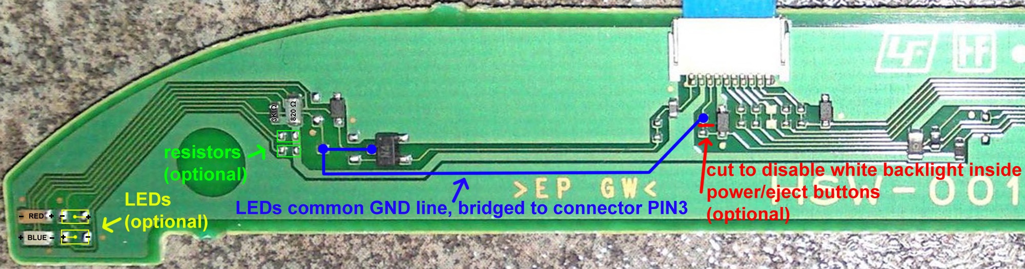
The blue line is a wire you need to solder in 3 points
And everythig i marked as "optional" is not needed
Also, the solder point most at left of the blue line is only needed if you are going to add the other leds
The reason why i soldered the blue line in 2 points at left is because this way you can control the 4 leds with only 1 line
dazzaXx
Member
So, the solder point on the very left hand side of the blue line is if you decide to add more LED's in? Basically its the one on the very right and the one next to the chip that has N4 on it?The tutorial of what i did is mostly this image, only is needed 1 wire
The blue line is a wire you need to solder in 3 points
And everythig i marked as "optional" is not needed
Also, the solder point most at left of the blue line is only needed if you are going to add the other leds
The reason why i soldered the blue line in 2 points at left is because this way you can control the 4 leds with only 1 line
EDIT: Just making sure as i have a 25xx and was thinking of doing this to mine.
sandungas
Developer
Yes, the easyest way to do it is this way:So, the solder point on the very left hand side of the blue line is if you decide to add more LED's in? Basically its the one on the very right and the one next to the chip that has N4 on it?
EDIT: Just making sure as i have a 25xx and was thinking of doing this to mine.

By doing it this way you can control the 2 leds that exists from factory (1 blue, and 1 red)
---------------------
And btw... if you want to disable the red led... the easyest way is by touching the red led with a solder iron in the center and add a lot of tin on top to melt both "pins" of the led... then push it laterally a bit with the solder iron to remove it
Dont get scared... of course by doing this the red led is going to be destroyed... but is imposible to desolder a led so tiny without destroying it anyway... so dont waste time trying to save it... if you decided to remove it is going to die anyway :P
The other alternatives to disable the red led is by desoldering the resistor connected to the led
Or by cutting a trace, but this is not a good idea (is easyer but is not needed, the other alternatives are better)
Cypher_CG89
Senior Member
@sandungas what LED's would I need to get and resistor's to add to the board of a CECH2003A to double them up with the optional empty slots on the PCB board?
Also this will come in handy for another mod I have been thinking of but no idea of how to implement it till now....would there be a way to use these pathways for these LED's, say the ones on the Motherboard to put LED's else where in the PS3's case but have the same colour coordination> Blue on, flashing blue for eject and red for standby?
Also this will come in handy for another mod I have been thinking of but no idea of how to implement it till now....would there be a way to use these pathways for these LED's, say the ones on the Motherboard to put LED's else where in the PS3's case but have the same colour coordination> Blue on, flashing blue for eject and red for standby?
sandungas
Developer
There is a formula to calculate the resistor for a given led... to do it accuratelly is needed to use in the formula some of the values that appears in the datasheet of the led manufacturer
https://www.kitronik.co.uk/blog/led-resistor-value-calculator/
https://www.kitronik.co.uk/blog/which-resistor-should-i-use-with-my-led/
The problem is usually we dont have the datasheet of the led manufacturer... and also the formula is going to give you a value for the resistor that will allow the led to emit the most light posible (inside the safe range)
Is safe... but lets say... is making the led to work at 100% workload
In the practise... we dont need the led to be working at full... is better to use a resistor with bigger values than the ones given by the formula
In general what everybody does is to use a resistor of 100ohm for the first test (because this should be enought and safe), and incase is emiting too much light replace the resistor by a much bigger value
For reference, look at the the resistors used in HSW-001 one of them is 820ohm (for blue) and the other 3000ohm (for red)... this means the red color have lower intensity
By playing with that you can achieve any color, are needed 3 leds in RGB and set the intensity of everyone of them with his resistor
The board have room for 4... so the 4th you can use a white led to change the brightness of the color generated by the others RGB
The leds in the switch boards of the PS3 works at 5v and are "SMD"... but under the category "SMD" there are different sizes, you need the smallest ones (i dont remember the exact size right now, maybe i wrote it in some place in wiki, take a look i guess i noted it somewhere)
And you can find them in ebay... i bought a pack of 100 (5 colors * 20 leds each) for 3€ free shipping or so
-----------------
The circuit of DSW-001 is a bit more tricky than HSW-001 because the DSW-001 PCB is "dual side" (it has circuits at both sides)
HSW-001 is a lot more straightforward because you have everything in the same side... so you can follow all the traces easilly
Right now i cant show you images of how people was doing this mod in DSW-001 but i remember to see some photos of it, you are going to need to search in google if you find something about it
Cypher_CG89
Senior Member
There is a formula to calculate the resistor for a given led... to do it accuratelly is needed to use in the formula some of the values that appears in the datasheet of the led manufacturer
https://www.kitronik.co.uk/blog/led-resistor-value-calculator/
https://www.kitronik.co.uk/blog/which-resistor-should-i-use-with-my-led/
The problem is usually we dont have the datasheet of the led manufacturer... and also the formula is going to give you a value for the resistor that will allow the led to emit the most light posible (inside the safe range)
Is safe... but lets say... is making the led to work at 100% workload
In the practise... we dont need the led to be working at full... is better to use a resistor with bigger values than the ones given by the formula
In general what everybody does is to use a resistor of 100ohm for the first test (because this should be enought and safe), and incase is emiting too much light replace the resistor by a much bigger value
For reference, look at the the resistors used in HSW-001 one of them is 820ohm (for blue) and the other 3000ohm (for red)... this means the red color have lower intensity
By playing with that you can achieve any color, are needed 3 leds in RGB and set the intensity of everyone of them with his resistor
The board have room for 4... so the 4th you can use a white led to change the brightness of the color generated by the others RGB
The leds in the switch boards of the PS3 works at 5v and are "SMD"... but under the category "SMD" there are different sizes, you need the smallest ones (i dont remember the exact size right now, maybe i wrote it in some place in wiki, take a look i guess i noted it somewhere)
And you can find them in ebay... i bought a pack of 100 (5 colors * 20 leds each) for 3€ free shipping or so
-----------------
The circuit of DSW-001 is a bit more tricky than HSW-001 because the DSW-001 PCB is "dual side" (it has circuits at both sides)
HSW-001 is a lot more straightforward because you have everything in the same side... so you can follow all the traces easilly
Right now i cant show you images of how people was doing this mod in DSW-001 but i remember to see some photos of it, you are going to need to search in google if you find something about it
On first glance... I do not like my switchboard lol. The link for the modding guide on the wiki is gone....the site no longer exists lol and google is not playing ball with my searches. But i will keep at it as this would be the key to customising my PS3s with LEDs in certain places. Like the PS3 logo on the top of the case:
Want it to look something like this.....
sandungas
Developer
Too much light for my taste, i just enabled one blue led because all i wanted was an small effect, the problem is the lightbar doesnt fills completly (just 1/6 or so like in your image)
From the DSW-001 circuit the only things i can say by looking at this photo...
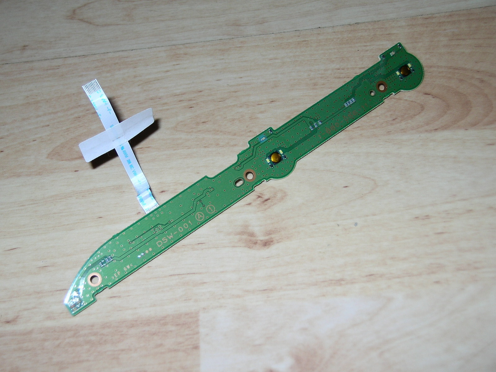
-The wide trace located inmediatly on top of the "DSW" letters is the 5v rail. At right is connected to a pin of the connector and the ribbon cable). At left is conected with the 4 resistors (one resistor for each led)
-The thin trace that is located inmediatly over the 5v rail is the line that turns ON/OFF this subcircuit we are talking about, if you flip the board back and forth you will realize everything at left of the connector (in both sides of the board) belongs to this subcircuit. At right goes to the connector and ribbon cable. And at left goes to the "base" pin of 2 transistors
-The transistors are at the other side of the board (and 2 diodes i guess like in HSW-001, are not mandatory thought, exists just for protecting voltage peaks in the leds)
So... if you want to make something similar of what i did you need to connect a wire in the "colector" pin of the transistors. The colector pin is the one directly connected with the ground (-) pin of the leds
In other words... the transistor is a "switch" that controlls the GND pins of the leds
If the transistor is OFF (because syscon is not sending the signal to the transistor base pin) then the GND pins of the leds are disconnected of the circuit
If the transistor is ON (because syscon is sending the signal to the transistor base pin) then the GND pins of the leds are connected to GND (this completes the circuit and the leds turns ON)
What we are doing in this mod is to "bypass" the transistor... we are connecting the GND pins of the "misterious" leds to the GND pins of other leds of the board (and btw, the other leds have transistors too that works exactly the same, but are located in the main motherboard)
Basically... you need to solder a wire from the "colector" pin of the transistor to the other pin of the connector you dedice is going to drive the leds
I did choose the pin for the white leds that creates the white backlight of the ON/EJECT buttons on PS3 slim, from factory this white leds are turned ON when PS3 is turned ON (i wanted it simple, also that lines have several white leds together so i thought adding one more was not going to cause any problem)
Luanteles mentioned he wanted to drive the leds together wih the red led that indicates standby (this would result in the leds of the mod to be enabled permanently, in standby and when PS3 is ON, a bit excesive imo)
I you want to control the leds of the mod in 2 groups you need 2 wires... and cut the trace that connects both "colector" pins of the 2 transistors... then solder a wire in each and connect the wires to different places
A good combination could be 2 leds controlled together with the white backlight (like i did), and 2 more leds controled together with the green light when you power ON the PS3 (the green led from factory does a cool triple "blink" when you turn ON anf OFF the PS3)
From the DSW-001 circuit the only things i can say by looking at this photo...
-The wide trace located inmediatly on top of the "DSW" letters is the 5v rail. At right is connected to a pin of the connector and the ribbon cable). At left is conected with the 4 resistors (one resistor for each led)
-The thin trace that is located inmediatly over the 5v rail is the line that turns ON/OFF this subcircuit we are talking about, if you flip the board back and forth you will realize everything at left of the connector (in both sides of the board) belongs to this subcircuit. At right goes to the connector and ribbon cable. And at left goes to the "base" pin of 2 transistors
-The transistors are at the other side of the board (and 2 diodes i guess like in HSW-001, are not mandatory thought, exists just for protecting voltage peaks in the leds)
So... if you want to make something similar of what i did you need to connect a wire in the "colector" pin of the transistors. The colector pin is the one directly connected with the ground (-) pin of the leds
In other words... the transistor is a "switch" that controlls the GND pins of the leds
If the transistor is OFF (because syscon is not sending the signal to the transistor base pin) then the GND pins of the leds are disconnected of the circuit
If the transistor is ON (because syscon is sending the signal to the transistor base pin) then the GND pins of the leds are connected to GND (this completes the circuit and the leds turns ON)
What we are doing in this mod is to "bypass" the transistor... we are connecting the GND pins of the "misterious" leds to the GND pins of other leds of the board (and btw, the other leds have transistors too that works exactly the same, but are located in the main motherboard)
Basically... you need to solder a wire from the "colector" pin of the transistor to the other pin of the connector you dedice is going to drive the leds
I did choose the pin for the white leds that creates the white backlight of the ON/EJECT buttons on PS3 slim, from factory this white leds are turned ON when PS3 is turned ON (i wanted it simple, also that lines have several white leds together so i thought adding one more was not going to cause any problem)
Luanteles mentioned he wanted to drive the leds together wih the red led that indicates standby (this would result in the leds of the mod to be enabled permanently, in standby and when PS3 is ON, a bit excesive imo)
I you want to control the leds of the mod in 2 groups you need 2 wires... and cut the trace that connects both "colector" pins of the 2 transistors... then solder a wire in each and connect the wires to different places
A good combination could be 2 leds controlled together with the white backlight (like i did), and 2 more leds controled together with the green light when you power ON the PS3 (the green led from factory does a cool triple "blink" when you turn ON anf OFF the PS3)
Last edited:
Cypher_CG89
Senior Member
Too much light for my taste, i just enabled one blue led because all i wanted was an small effect, the problem is the lightbar doesnt fills completly (just 1/6 or so like in your image)
Yeah it's not to everyone's taste the way I want it, just looks like this atm: ( I photo shopped in where i wanted the extra light to be compared to where it is now, just on the PS3's 4 USB hub base stand which I customised to holed a Superslim as well. )
This is my main PS3 I use for modding stuff/ and dev work, in the process of putting a 1TB HDD in it for the 680GB that's already in it so when am done am going to do this mod first then work out how am going to do the other one for the PS3 logo as it going to need cutting out of the case first, The other 2TB PS3 is in the front room and am not touching it...yet lol.>
Yeah the effect is the same as luenteles described. Permanent enabled but changing colour from red to blue when switched on, would be cool if they flashed on boot and shutdown of the console as well.
If you don't mind could you do a few basic squiggles on the pic of where the wires would go on the PCB board and the cut points for both your way and the other way. Doesn't have to be perfect, am not a complete dunce when it come to this sort of stuff just a ruff idea of where things would go and I'll figure the rest out. Would be greatly appreciated.
sandungas
Developer
The photos in wiki of the DSW-001 board are not good enought to see the circuit, im sure is going to be pretty much like the HSW-001 but i cant tell you where to solder or whatever :/
Btw... if what you want is to have the "misterious leds" enabled when the PS3 is in standby the mod is a lot easyer than what i was suggesting
The only thing you need to do is to connect the GND pins of the leds to GND (there are a lot of available GND areas all around, choose the easyest, or the closest)
Im not much into leds, but i love this invention btw, is named "ambilight" and is patented by philips (and they holds the patent until not sure when so other TV manufacturers cant use it, and that sucks)
And... not sure if you knew it, but search in google for "clear epoxy resin" maybe comes in handy for what you want to do, initially is very fluid (like honey), you need to prepare a "mold" of silicone... then drop the resine in it and "hit" it a bit (to take out the bubbles), then let it dry and the result is awesome... is like glass
I remember to see a "do it yourself" tutorial using it to create transparent buttons for a gamepad (or a portable console), and the result was awesome, like made by a machine
Edit: Found it
Last edited:
Cypher_CG89
Senior Member
The photos in wiki of the DSW-001 board are not good enought to see the circuit, im sure is going to be pretty much like the HSW-001 but i cant tell you where to solder or whatever :/
Btw... if what you want is to have the "misterious leds" enabled when the PS3 is in standby the mod is a lot easyer than what i was suggesting
The only thing you need to do is to connect the GND pins of the leds to GND (there are a lot of available GND areas all around, choose the easyest, or the closest)
Im not much into leds, but i love this invention btw, is named "ambilight" and is patented by philips (and they holds the patent until not sure when so other TV manufacturers cant use it, and that sucks)
And... not sure if you knew it, but search in google for "clear epoxy resin" maybe comes in handy for what you want to do, initially is very fluid (like honey), you need to prepare a "mold" of silicone... then drop the resine in it and "hit" it a bit (to take out the bubbles), then let it dry and the result is awesome... is like glass
I remember to see a "do it yourself" tutorial using it to create transparent buttons for a gamepad (or a portable console), and the result was awesome, like made by a machine
Got plenty of apoxy resin in the garage, that stuff is lethal, You can bond nearly anything together with that stuff. I use it on cracked plastic panels on cars whether its a bumper, trim or interior panel > some of that on the back with another bit of plastic to reinforce it. make for a good quick fix. If on bumper trims then all you do is prep the painted surface by sanding it down, fill with body filler, sand it down when set, prime, colour, lacker = good as new and strong again. no wasting hundreds on a new one or looking for a replacement. never thought about using it like that though.....
Al use the pics you put up of the other switch board and I'll figure it out form there. The PS3 logo i want to change the same way this switchboard light will. RED> standby, Blue> PS3 on. I suppose if I wire from the same points as where I would for the switch board LEDs they and use the same colour LEDs then technically it should work.... i think lol.
I like them LEDs but I hate Phillips TVs, there a pile of shite. The only one I had decided that after years of use it would refuse to power on. The cause of this was > a stupid tiny glass fuse in the power on circulate on the TV's switch board, could i hell find a replacement for it. even rang phillips and they wanted ridiculous money for this fuse so it went in the skip, mind it was one of the first flat screen LCD HDTVs made lol.
Cypher_CG89
Senior Member
My CECH2003A
You little thief.... I have 2 CECH2003A's and was wondering here one of them had gone? give it back.....


No stealing my idea for the PS3 logo.....
its copyrighted and patented....Similar threads
-
PS3 CECH-3004B (slim) on 4.93 and HEN installation/enablement issues
- Started by temenori
- Replies: 1
-
 PS3 PS3 New Paste Questions / Broken BD Ribbon Cable (SS)
- Started by RinMaru90
- Replies: 5
-
PS3 slim solid red light after cleanning dust and repast
- Started by fowly
- Replies: 0
-
PS3 PS3 slim 3001a turns on without problem, but shut off after a minute
- Started by Reisver
- Replies: 3