evaldas256
Member
I fixed it, for a minute (the CECHG). This is the first time i saw it run.It would be pure speculation at this point to say for sure.
The question too would be has anyone here been able to revive a SEM-001 motherboard with a tantalum cap replacement?
Reading through all of the posts, I don't remember if anyone has.
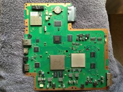
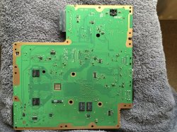
The system now has 14 470uf 10V caps (yellow chinese cheapies) + 1 old Tokin per chip. I used a hair drier, hottest setting, on the whole board, both sides, focused on the last two Tokins especially and it actually fired up. Then it ran for a minute, shut down, ran only for five seconds, shut down, then two. And the same thing happens every time i let it sit for 10+ minutes.
So i guess i kind of revived the two tokins with heat? Or could this be not tokin related?
I would love to hear some opinions. And i guess, what guage wire and how many wires should i use for the bridging?

P.S. Video is green because i'm using RGB Scart.

")
