You are using an out of date browser. It may not display this or other websites correctly.
You should upgrade or use an alternative browser.
You should upgrade or use an alternative browser.
PS3 (Research/Experimental) - NEC/TOKIN Capacitors Replacement - YLOD
- Thread starter Naked_Snake1995
- Start date
Maroon Storm
Member
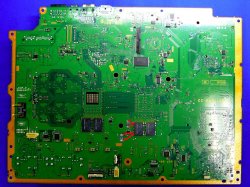
So, I've got cecha12. I'm very happy. Looks clean. I'm anxious. I think I'm going to solder the tantrums 1 or 2 or more on this side: https://www.psdevwiki.com/ps3/images/d/da/COK-001_BOTTOM.JPG, with PATA cable wire. Is it a good idea? I think something like this:
Attachments
Naked_Snake1995
Senior Member
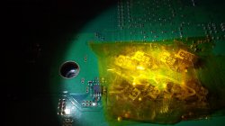
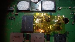
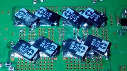
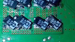
Interesting, for once, ill hear you out, its seems rather an interesting finding.Sorry, was gonna peace out, but since I really am actually trying to help, I have to share these last two images before I go. I just finished switching my test console over to completely tantalum so I could get these images. This is 4x 330uF per tokin.
GPU idling:

CPU idling:

While it works perfectly, the sustained spikes on the GPU line (spending about 10% duty at 1.6 volts now) and the overall increase in voltage on the CPU line (0.06V increase on average) are suuuuuper bad in the long run. Also note that this isn't even under load, just idling. Overvolting a chip directly decreases its lifespan and quickens electromigration. Ask the overclockers, or buy a GPU from a crypto miner.
Actual NOS tokins are still available. Please consider using them instead of tantalum. If not, the increase is likely due to tantalum having a slightly higher ESR than the polymer tokins. The tokins are rated at 1 milliohm ESR. Get as close to that as possible to minimize the impact of overvolting.
Alright, now I'm off to reball some pancakes and bacon. Peace!
Still a bit odd that the GPU now operates a 1.6V (correct me if wrong) are GPUs and CPUs of that circa 2005 all operate at 1.5V or below?
If i recall correctly the NECs have a rated operating voltage at 2.5V i believe, but the most interesting is the same ripple are you showing on the Tantalums, is the same ripple behaviour found on the NECs in other scenarios, not just the PS3s, so something is missing out.
I do have to agree for once, that a better understanding of how much voltage the Tantalums needs to be, usually the operating voltage is carried by the Voltage Regulators, so it shouldn't affect the operating voltage in the processor, as long as the Tantalums are at the same rated voltage, as the NECs, the 2100 Series and upwards all use 470uF Tantalums,and they're feeding system wasn't drastically redesigned, apart the removal of a few vias to accommodate the Tantalums, otherwise they use the same Voltage Regulators as the previous models, in that case the 2100 Slims then have a higher operating voltage, which is not the point of a more efficient console.
At the moment i cannot find non of the operating voltage for the CELL B/E or even the RSX, even by searching a 7800GTX variant.
Yes, you could use the same NECs as the original came in, nothing wrong with that, is the best solution, but can't guarantee reliability, unless the newest batch of NECs increased reliability, but i highly doubt it, since in todays equipment they are non-existent,thats where Tantalums comes in, but the best method i found, at least for me, is to have a 50/50 method, half NECs and Half Tantalums, thats how my 60Gb got it.
Another thing i should point out, is yes, the Tantalums do have a slightly higher ESR capacity, although it doesn't affect the operating process, another type of capacitor which is also advised are the NEON Capacitors (hope is pronounced right) , although i don't know how they look like, repair shops who used them as an alternative to Tantalums, and apparently they have the same ESR capacity as the NECs.
Sent from my G8141 using Tapatalk
Last edited:
Suppose an idea is to have the board out with some heatsink or custom water blocks cooling the cell and rsx this way all the board is exposed for dmm testing while in idle and loaded state this way we can compare test results.
According to the internet based on the voltage on 7800gtx it usually called vcore but mainly gpu voltage it said it runs at 1.25v there about but that depend on the core speed but the reason it showing higher voltage is because the memory is build into the chip. Did this slip everyone's mind??
According to the internet based on the voltage on 7800gtx it usually called vcore but mainly gpu voltage it said it runs at 1.25v there about but that depend on the core speed but the reason it showing higher voltage is because the memory is build into the chip. Did this slip everyone's mind??
Last edited:
Gus21
Member
PS:Ill also leave a snapshot of the NECs replaced on the RSX side, for anyone whos intrested, i see i have many questions on this thread, and a few messages on my inbox, unfortunately i will not answer anything today, ill answer them tommorow.

Hello, the other side of the pcb did you remove one or more nec/tokin? Or Didn't remove any nec/tokin?
Hello, the other side of the pcb did you remove one or more nec/tokin? Or Didn't remove any nec/tokin?
Last edited:
Gus21
Member
Yes, you could use the same NECs as the original came in, nothing wrong with that, is the best solution, but can't guarantee reliability, unless the newest batch of NECs increased reliability, but i highly doubt it, since in todays equipment they are non-existent,thats where Tantalums comes in, but the best method i found, at least for me, is to have a 50/50 method, half NECs and Half Tantalums, thats how my 60Gb got it.
Sent from my G8141 using Tapatalk[/QUOTE]
You didn't show any screenshots on the other side of the pcb, I would like to know if you removed one, two or no nec / tokin on this side of the pcb.
You recently commented that your ps3 got 50% tantalum and 50% nec / tokin.
Would you like to show the screenshot on both sides of the pcb to help us all or make a drawing showing how it was.
Maroon Storm
Member
Yes you right. That cable is in several filament, it doesn't good.Pata cable you mean ide cable
Basically I just give up the piggyback idea. I just followed the first post steps and the suggestions about how to remove the nec's with heat. Burning them down is better than scraping them with care but it is still damaging to the board. You cannot avoid scratches.Hello, the other side of the pcb did you remove one or more nec/tokin? Or Didn't remove any nec/tokin?
I'm going to update this post or the next one with screens, but now I just removed 3 NEC's under the RSX (2 bottom, 1 top) but the cecha12 doesn't boot. On the slim, I replaced all 4 this one doesn't boot either. I've worked on these machines hours upon hours day after day but no success. I've collected a couple of spare machine recently.You didn't show any screenshots on the other side of the pcb, I would like to know if you removed one, two or no nec / tokin on this side of the pcb.
I checked the connections with multi-meter. The corresponding sides are connected ground to ground positive to positive and the tokins also connected on the two sides.
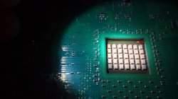
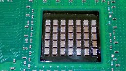
But I'd catched something on the cecha12 CELL under where are those little elements (maybe ceramic resistors) on it. The CELL itself has a hump (the shape is convex) one of the corner and I can push a little bit back I certain I pushed that hump back as I tried it a couple of times. I don't know It is a problem or not.Maybe I need to replace more NEC's under the CELL or the CELL is dead on it because I found traces (left over flux) of reheating or re-balling.
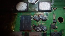
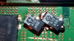
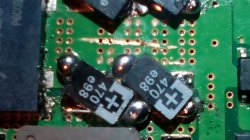
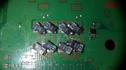
I've recently realized replacing the bottom part NECs' are the easiest ones the real deal is the top part (basically under the cooler). Those silver components and lots of little resistors all over the place. Without question I try to solder them as flat as I can.
Attachments
-
 IMG_20191207_180125.jpg696.3 KB · Views: 385
 -
 IMG_20191207_180220.jpg409.8 KB · Views: 347
 -
 IMG_20191207_180231.jpg450.6 KB · Views: 350
 -
 IMG_20191207_182022.jpg609.6 KB · Views: 367
 -
 IMG_20191207_182041.jpg578.9 KB · Views: 382
 -
 IMG_20191207_182058.jpg473.3 KB · Views: 373
 -
 IMG_20191207_182109.jpg480.1 KB · Views: 350
 -
 IMG_20191207_182202.jpg412.9 KB · Views: 337
 -
 IMG_20191207_182318.jpg548.4 KB · Views: 376
 -
 IMG_20191207_182357.jpg535.9 KB · Views: 371
 -
 IMG_20191207_182453.jpg563.9 KB · Views: 371
 -
 IMG_20191207_182457.jpg539.7 KB · Views: 401
 -
 IMG_20191207_182931.jpg707.3 KB · Views: 363
Last edited:
Gus21
Member
Yes you right. That cable is in several filament, it doesn't good.
I've recently realized replacing the bottom part NECs' are the easiest ones the real deal is the top part (basically under the cooler). Those silver components and lots of little resistors all over the place. Without question I try to solder them as flat as I can.
Thank you for the report.
Naked_Snake1995
Senior Member
Yes, you could use the same NECs as the original came in, nothing wrong with that, is the best solution, but can't guarantee reliability, unless the newest batch of NECs increased reliability, but i highly doubt it, since in todays equipment they are non-existent,thats where Tantalums comes in, but the best method i found, at least for me, is to have a 50/50 method, half NECs and Half Tantalums, thats how my 60Gb got it.
Sent from my G8141 using Tapatalk
You didn't show any screenshots on the other side of the pcb, I would like to know if you removed one, two or no nec / tokin on this side of the pcb.
You recently commented that your ps3 got 50% tantalum and 50% nec / tokin.
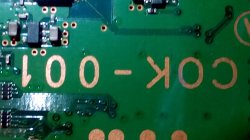
Would you like to show the screenshot on both sides of the pcb to help us all or make a drawing showing how it was.[/QUOTE]Is the same procedure, but sure, this is how i made, take the 1st picture of mine you reposted, correct, thats my motherboard COK-002,as you can see the top-side (although correctly is the bottom-side in the manual) where the processors aren't present, are paired with Tantalums, now take the 2nd picture and you can see there are only NECs, leave that as it is, don't touch them.
There you have it, replace only the top-side and leave the ones near the processors in NEC Stock.
Sent from my G8141 using Tapatalk
Naked_Snake1995
Senior Member
Is the same procedure, but sure, this is how i made, take the 1st picture of mine you reposted, correct, thats my motherboard COK-002,as you can see the top-side (although correctly is the bottom-side in the manual) where the processors aren't present, are paired with Tantalums, now take the 2nd picture and you can see there are only NECs, leave that as it is, don't touch them.
There you have it, replace only the top-side and leave the ones near the processors in NEC Stock.
The reason why there isn't any bottom board screenshots is because mine still have the original NECs present, it doesn't have any Tantalums attached, so why would i post a NEC board? When i fully disclosed that topic, 50/50 means half Tantalums and half TOKINs, being that the top-side having Tantalums and the bottom side having NECs.
Sent from my G8141 using Tapatalk
Gus21
Member
[QUOTE = "Naked_Snake1995, post: 217804, membro: 32795"] É o mesmo procedimento, mas com certeza, foi assim que fiz, tire a 1ª foto minha que você publicou, correta, é a minha placa-mãe COK-002, como você pode veja o lado superior (embora corretamente seja o lado inferior no manual) onde os processadores não estão presentes, estão emparelhados com o Tantalums, agora tire a segunda foto e você pode ver que existem apenas NECs, deixe como estão, não toque neles.
Lá está, substitua apenas a parte superior e deixe as próximas aos processadores no NEC Stock.
A razão pela qual não há capturas de tela da placa inferior é porque as minhas ainda têm os NECs originais presentes, ele não tem nenhum Tantalums anexado, então por que eu postaria uma placa NEC? Quando eu divulguei completamente esse tópico, 50/50 significa metade de tântalo e metade de TOKINs, sendo que o lado superior com tântalo e o lado inferior com NECs.
Enviado do meu G8141 usando Tapatalk [/ QUOTE]
Thanks
wrx884
Member
But I'd catched something on the cecha12 CELL under where are those little elements (maybe ceramic resistors) on it. The CELL itself has a hump (the shape is convex) one of the corner and I can push a little bit back I certain I pushed that hump back as I tried it a couple of times. I don't know It is a problem or not.Maybe I need to replace more NEC's under the CELL or the CELL is dead on it because I found traces (left over flux) of reheating or re-balling.
Hey mate is this the hump ur referring too? just trying to find it myself, if so since there is evidence of flux from a reflow its highly possible the CPU has been de-laminated (pop corned), if so then it will be no good unfortunately.
Also if these are not test boards make sure u remove the old thermal adhesive from the GPU's rams so when u pop the IHS back on it sits nice and flush back on GPUs dies surface. Same with the under side of the IHS make sure thats free from any adhesive and clean too.
Maroon Storm
Member
Yes, that is it. I have some spare ps3s. Is any ps3 cell good to replace that?View attachment 21417
Hey mate is this the hump ur referring too? just trying to find it myself, if so since there is evidence of flux from a reflow its highly possible the CPU has been de-laminated (pop corned), if so then it will be no good unfortunately.
Also if these are not test boards make sure u remove the old thermal adhesive from the GPU's rams so when u pop the IHS back on it sits nice and flush back on GPUs dies surface. Same with the under side of the IHS make sure thats free from any adhesive and clean too.
Naked_Snake1995
Senior Member
It isnt that easy to just replace the CELL and off you go lad, as far as i know, CELL is paired with the NOR/NAND Memory and the SysCon, so thoes have to be changed as well, many people dont replace the CELL only for the hassle to replace the rest of the required parts, but its up to you to see if is worth the try.Yes, that is it. I have some spare ps3s. Is any ps3 cell good to replace that?
And not any CELL is good for a replacement, you need a board specific CELL, lets say you have a COK-001 with a dead CELL, youll need the same COK-001 board to perform the transplant, i think you could use a COK-002 as well,but the PS2 Hardware Detection is what bothers me,it could be NAND related, so the best is to stick with the specific board Version.
Just wanted to thank the OP and report a success using this method to fix the YLOD in a Phat PS3 (Model CECHG02).
I found the console thrown out on the street but it would not start, exhibiting the YLOD. I decided to replace all the nec-tokin caps on the top layer, leaving them alone on the underside where I may have damaged the board. I used 4x 470uF 4V caps to replace each of the 4 nec-tokins, and now starts up just fine.
Although the unit is old and the thermal paste probably dried up I have left the "delid" of the two main chips for another day... for now I am just very happy to have a working PS3. I'll put it through it's paces in the coming weeks.
A pic attached. Thank you for sharing this awesome fix!
Dmitriy Semenov
Forum Noob
[QUOTE = "Eld, post: 217907, member: 52928"] Просто хотел поблагодарить OP и сообщить об успешном использовании этого параметра для исправления YLOD в Phat PS3 (модель CECHG02).
Я нашел консоль на улице, но она не запустилась. Я решил заменить все колпачки на верхнюю часть слона. Я использовал 4x 470 мкФ 4V колпачки, чтобы заменить каждый из 4-х токенов, и теперь запускается просто отлично.
Хотя устройство старое и термопастное, вероятно, у меня есть, я хочу, чтобы PS3. Я проверю это в ближайшие недели.
Фото прилагается. Спасибо, что поделились этим удивительным исправлением!
[/ QUOTE]
you accidentally did not mix up the polarity when soldering?
Я нашел консоль на улице, но она не запустилась. Я решил заменить все колпачки на верхнюю часть слона. Я использовал 4x 470 мкФ 4V колпачки, чтобы заменить каждый из 4-х токенов, и теперь запускается просто отлично.
Хотя устройство старое и термопастное, вероятно, у меня есть, я хочу, чтобы PS3. Я проверю это в ближайшие недели.
Фото прилагается. Спасибо, что поделились этим удивительным исправлением!
you accidentally did not mix up the polarity when soldering?
Maroon Storm
Member
I'm so angry because of that lamination problem. So It is for sure a bad unit. I can't fix this one. The slim also doesn't work I replaced all the necs on that one. Also I couldn't fix the cechc model. I've seen mymatevince newest video where he could manage to fix his phat with 4 capacitors but it was a G model. I really want to fix the slim at least, but it has more problems what I don't think I could fix.It isnt that easy to just replace the CELL and off you go lad, as far as i know, CELL is paired with the NOR/NAND Memory and the SysCon, so thoes have to be changed as well, many people dont replace the CELL only for the hassle to replace the rest of the required parts, but its up to you to see if is worth the try.
And not any CELL is good for a replacement, you need a board specific CELL, lets say you have a COK-001 with a dead CELL, youll need the same COK-001 board to perform the transplant, i think you could use a COK-002 as well,but the PS2 Hardware Detection is what bothers me,it could be NAND related, so the best is to stick with the specific board Version.
Naked_Snake1995
Senior Member
MyMateVince, i saw a few of his videos, shame he did ruined that C04 with a torturous reflow, i see he had success with the G model, although he used electrolyte capacitors, honestly i expected a bang, but guess that works too, what a madlad [emoji23][emoji23]Hey naked snake your method popped up againthis time different caps
I expect Steve from TronicsFix to work on this topic too, but unfortunately as far as i am aware, he doesn't work with PlayStation3s, as he owns a repair shop, is not really a good business to repair consoles that for him aren't worth selling,but he might be generous enough to try it.
Sent from my G8141 using Tapatalk
Similar threads
-
 PS3 Interesting PS3 Errors (1802, 1701, 1601) and Capacitor Replacement
- Started by Cheshire UK
- Replies: 2
-
PS3 CECHA00 with several SYSCON errors (3004, 1001,1002, 2120,3011)
- Started by LSL
- Replies: 7
-
PS3 A0801002 after 4 nec/tokin replacement (maybe Felix or anyone help me)
- Started by Swhalegod
- Replies: 3
-
Hello newcomer to the ps3 modding scene, needing help with syscon diagnostic
- Started by ascendantprime
- Replies: 1