Hey fellas,
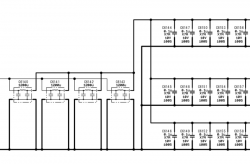
so here's the block diagram for the section that includes the tokins. This is for the bottom side of the board, but the top side is identical.
https://imgur.com/AlICNjJ
It's a little hard to read, but it basically says that the RSX has 4 tokins connected to it (2 on each side of the board), and the positive side of the NECs have all to be connected to each other. The CELL tokins are not directly related to the RSX ones. When you remove all four of the NECs, that positive connection disappears, hence the need for the bridge wire. You NEED to have those positive poles connected together.
See the image below. It only shows the two tokins on the top side of the board for the RSX, but via's on the board connect them to the tokins on the bottom side as well.
https://imgur.com/AlICNjJ
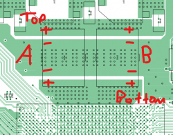
I did a bit of testing yesterday, and here's what I determined: With the RSX jumper wire installed, ALL the positive sides for the RSX tokins are connected. This means that you should have continuity from the TOP A +, all the way down to the BOTTOM B +. This one wire also enables connectivity with RSX tokins on the bottom half of the board. If you're replacing all 4 tokins on the Cell side, you'll still need a jumper wire on that side, but just one!
Even without the wire, A and B are always connected on the BOTTOM +, and A and B are always connected on the TOP + (negatives are always connected no matter what). But the jumper wire connects TOP + and BOTTOM + together, completing the circuit.
What I can also determine is that you don't need TWO wires per 4-tokin set (I've even seen people add 4 wires per set -- two on the bottom half of the board and two on the top half).
Finally, without the jumper wires, the board will power up, but you will get the fastest YLOD of your life, probably < .5 seconds. This is not a short circuit, it's just a lack of continuity.
EDIT: not sure why my images are not showing up in line. If someone can help clarify what I did wrong, I'd appreciate it! In the meantime, the images are also attached.

")