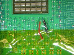
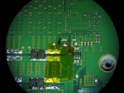
Probe set to 10x and Scope set to 10x. Probing CPU through convenient hole in the RF shielding on the BTM side of the motherboard. The probe is propped up so I don't have to hold it (Holding it actually increases the noise).
This is the entire YLOD event. Power increase from 0v to ~1.3v upon powering on (Rise). The voltage is steady on the plateau (the area I'm interested in to evaluate cap health and VRM performance) for half a second until the YLOD occurs and the voltage drops back to 0v with a characteristic transition as the caps discharge (fall). Notice this is DC coupled and the BW limit is off. I'm also not using High-Rez Aquire mode yet.
Closeup of the rise. 2.5ms for the voltage increase, not sure if that matters, but I did test it with another Power supply and it didn't change (for this motherboard). I don't know if this could be important to measure or not, but I wanted to record it juz cuz.
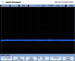
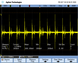
And even closer look now. 50mV/div, not much noise.
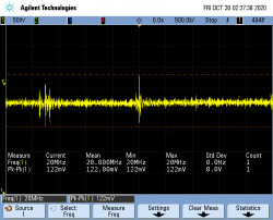
Fully zoomed in on the vertical axis now. 10mV/div. Aquire mode is normal and while the Vpp says 30mV looks more like 20mV.
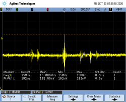
Decided to try out the High-Res Acquire Mode here. That really cleaned up the noise and allow us to see the sawtooth pattern. I'm was expecting this to be the VRM maintaining the voltage, but I wonder if it's charge/discharge cycles of capacitors. The switching frequency of the DC-DC switching regulator is 300KHz - 1 MHz. The frequency of these pulses appears to be more like 2 per division. 1uS/div is 1MHz/div. So 2 pulses per division is ~2MHz.
This is the same image zoomed in on the horizontal axis a little, just to see the sawtooth charge discharge cycles a bit easier. From these, I can't see anthing that would lead me to believer the Capacitors are not doing their job. This is a nice clean DC voltage.
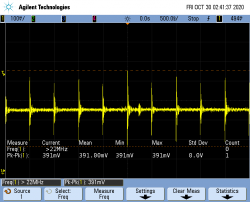
And here is where the YLOD occurs. I figured if I recorded the rise time, why not the fall time as well. 32.1mS before the voltage returns to 0 after a YLOD.


")