PS3 (Research/Experimental) - NEC/TOKIN Capacitors Replacement - YLOD

Would you be able to link some delidding tools as mine is giving me bad luck this year 4 bc ps3 killed by delidding so far annoyed af and last year everything was perfect this year just isnt my year i guess aha so yeha link me to some of them plastic razor blades that seems like a good idea as they shouldn't scratch the cpu like metal ones cheers
You need to make a custom delidding tool.

There used to be an off the shelf delidding tool, but I can't remember what it's called. And I don't they they are still made.
 
Would you be able to link some delidding tools as mine is giving me bad luck this year 4 bc ps3 killed by delidding so far annoyed af and last year everything was perfect this year just isnt my year i guess aha so yeha link me to some of them plastic razor blades that seems like a good idea as they shouldn't scratch the cpu like metal ones cheers
You can also use a 0.08 mm LCD screen cutting line, and I did that on mine and it was successful, I even tested it on the South bridge and it worked too.
https://www.psx-place.com/threads/delidding-south-brigde-from-cecha-b-c-e.36713/
 
Yo, just popped open a 2001 slim and it has bad TOKINs on the GPU! I don't do slims normally, so this is the first bad set I've seen on a slim.

Random length YLOD, and o-scope verifies bad caps. Waveform is a straight up rectified sine wave coming in at 80mV. I don't know how to grab error codes from a slim and I can't manage to find a guide buried in all the new info. If someone points me to the connection spots for a DYN-001, I'll update with the error codes.
here is what you need: https://www.psdevwiki.com/ps3/File:DYN-001_SC_UART_testpads.jpg
 
Is there anything else different I need to do for slims versus the fat boys I normally handle? I keep getting AUTH1 response invalid. Switched Rx and Tx back and forth a few times just to be sure that wasn't it....
 
Also, I browsed a few pages back and noticed some discussion about adhesives. I use Permatex Red RTV gasket maker on the CELL, and Stars-922 heatsink plaster on the RSX. While it says plaster, when cured it is flexible and removable. I would not use epoxy for the sake of easier future service.

Use both sparingly. The red I use a thin line from an 18 gauge syringe, and each chip on the RSX gets a "grain of rice" worth of plaster on it.
 
Yo, just popped open a 2001 slim and it has bad TOKINs on the GPU! I don't do slims normally, so this is the first bad set I've seen on a slim.

Random length YLOD, and o-scope verifies bad caps. Waveform is a straight up rectified sine wave coming in at 80mV. I don't know how to grab error codes from a slim and I can't manage to find a guide buried in all the new info. If someone points me to the connection spots for a DYN-001, I'll update with the error codes.
Check the links in my signature for my SYSCON guide

Slims use SW instead of CXR or CXRF
 
Alrighty, got it working. Thanks, guys! 2 problems, 1 was the SW you mentioned, 2 was I have a very, very outdated syscon script. So...

Oscilloscope verified bad RSX caps on a DYN-001 with random length shutdowns (3 - 20 seconds) produce A0801002 by itself.

Didn't feel like saving the image so I just took a picture with my phone because I'm lazy.
wppm1UT.png
 
Last edited:
I got it same situation in 2018 after few days reball they were failing or glod. Were like 3 or 4 boards. I did not exchange any caps until this syscon diag was released in 2020. All dyn001 have tantal since then. I was confident reball went fine. After all tantal were exchange on those boards were working fine. One was doing even green artefacts when playing then working fine. So that is very sensitive area for power vddc. On dyn001 10 caps are good enough. It is totally 4000 uf.
 
Some success to report in fixing my YLOD slim. I replaced the each of the two NEC / Tokins on the underside of the board with four Panasonic 330uF tantalum caps . The PS3 now performs flawlessly. Thanks @Workz_777 for sharing your method of using kapton tape to insulate the negative strips. I think any other method could've easily resulted in a short due to my limited soldering skills.

Sorry to bump this old post, are they insulating the negative solder pads/strips to prevent the tantalums from bridging the outer solder pads to them?

the center section where the mask has been removed, that's essentially the same plane as the inner solder pads right?
 
Sorry to bump this old post, are they insulating the negative solder pads/strips to prevent the tantalums from bridging the outer solder pads to them?

the center section where the mask has been removed, that's essentially the same plane as the inner solder pads right?

Yep, because when soldering the tantalums on a diagonal it's easy to (by accident) short the (+) and (-) with the strips, so to prevent that tape over (with Kapton tape) the negative strips - then de-mask the center section (which is also (-) ground) and solder the negative of the tantalums there. Also that way you can solder them straight rather than on a diagonal.
 
According to the syscon log there's still 1001-1004 errors. I've changed the caps many times over. I checked the meter I'm getting around 15 ohms for both cpu and gpu side. It's a bit too high?
Maybe I'm putting too many caps. I'm using 470uF 6.3v caps.
 

Attachments

  • 275487366_1371922469922732_5572086002396438937_n.png
    275487366_1371922469922732_5572086002396438937_n.png
    46.6 KB · Views: 88
  • 275732569_364153682269063_1835434411399836782_n.jpg
    275732569_364153682269063_1835434411399836782_n.jpg
    109.8 KB · Views: 85
  • 275647654_3324748201094787_3868038633279551555_n.jpg
    275647654_3324748201094787_3868038633279551555_n.jpg
    93 KB · Views: 83
  • 275900272_1134469537330937_443452506745931481_n.jpg
    275900272_1134469537330937_443452506745931481_n.jpg
    87.4 KB · Views: 79
  • 275576509_933891127323195_5250573534769924347_n.jpg
    275576509_933891127323195_5250573534769924347_n.jpg
    102.1 KB · Views: 85
  • 275562372_263254489336255_2381354763253395512_n.jpg
    275562372_263254489336255_2381354763253395512_n.jpg
    92.9 KB · Views: 86
  • 275834329_510240537265181_3505993417024045129_n.jpg
    275834329_510240537265181_3505993417024045129_n.jpg
    112 KB · Views: 82
According to the syscon log there's still 1001-1004 errors. I've changed the caps many times over. I checked the meter I'm getting around 15 ohms for both cpu and gpu side. It's a bit too high?
Maybe I'm putting too many caps. I'm using 470uF 6.3v caps.

Hi @cryptblood1986, few things...

1) Those AVX caps are really not the right ones to use for this purpose. You want 2.5V and not 6.3V for starters. Then the ESR is too high with those AVX tantalums. These are the tantalums you would want to use in an ideal world:- Panasonic 470uF 2.5V 7mΩ@100kH (and not the cheap Panasonics from Aliexpress or the cheap Panasonics on eBay - because those will be either fake, or worse, quality control throw-aways) ...you want the A-Class (real) ones (see links below) part number: 2R5TPE470M7

Links for them here, yeah they cost more, but gold costs more than copper, and we get what we pay for. ;)

Mouser:-
https://www.mouser.com/ProductDetail/Panasonic/2R5TPE470M7?qs=OE1iw1LrrPFssbKV91yTww==

Digi-Key:-
https://www.digikey.com/en/products...4880?s=N4IgTCBcDa4EoFYAqAFAogFgOwAYCyWIAugL5A

2) Three 470uF per Tokin replacement is what you should aim for.

3) Some of your AVX tans are burnt, and probably not working well as a result.

4) By soldering Tantalums on a diagonal, as per your photos, you risk shorting them because the (+) and (-) contact strips on the board are so close together that it's easy done. Instead, cover over the negative contact strip on the board with some Kapton tape, sand the middle area so you see copper, and then solder the tantalums straight with the negative side soldered to the new de-masked middle area.

See photo here for preparation, click on image to see better.

PS3_caps_desoldered.JPG
 
hello guys today i found a guy that he made a tutorial to prevent the heat on ps3 fat and slim the man speaks most of the video in Arabic but he explain things in English hope it's use full

 
Hi @cryptblood1986, few things...

1) Those AVX caps are really not the right ones to use for this purpose. You want 2.5V and not 6.3V for starters. Then the ESR is too high with those AVX tantalums. These are the tantalums you would want to use in an ideal world:- Panasonic 470uF 2.5V 7mΩ@100kH (and not the cheap Panasonics from Aliexpress or the cheap Panasonics on eBay - because those will be either fake, or worse, quality control throw-aways) ...you want the A-Class (real) ones (see links below) part number: 2R5TPE470M7

Links for them here, yeah they cost more, but gold costs more than copper, and we get what we pay for. ;)

Mouser:-
https://www.mouser.com/ProductDetail/Panasonic/2R5TPE470M7?qs=OE1iw1LrrPFssbKV91yTww==

Digi-Key:-
https://www.digikey.com/en/products...4880?s=N4IgTCBcDa4EoFYAqAFAogFgOwAYCyWIAugL5A

2) Three 470uF per Tokin replacement is what you should aim for.

3) Some of your AVX tans are burnt, and probably not working well as a result.

4) By soldering Tantalums on a diagonal, as per your photos, you risk shorting them because the (+) and (-) contact strips on the board are so close together that it's easy done. Instead, cover over the negative contact strip on the board with some Kapton tape, sand the middle area so you see copper, and then solder the tantalums straight with the negative side soldered to the new de-masked middle area.

See photo here for preparation, click on image to see better.

View attachment 36678
I have nothing to add except that you can get those caps at about half the price from LCSC. About $22 for 24 of them, which will be enough to recap the whole board. And they are genuine high quality. LCSC is the parent company of JLCpcb, which if you watch YT you may recognize. In fact if you order PCB's from JLCpcb they can assemble them with LCSC parts numbers, if you provide them with the Bill of materials.

I am looking into having them assemble my Tantalizers this way.
 
Tbh nectokins fails more on the 80gb and 40gb ps3 i think that why it happens on 80gb and no solder cracks is because the board is smaller and is more surrounded by mounting holes making the board flexing less during the heat as for the 60gb the board is very big with fewer mounting holes especially around in the middle of the board and around it in the left and rear and if you look at the 60gb heat sink the blocks move from the heat pipes so it flexes more and on the 80gb its two separate heat sinks that push agains the bottom heat shield for the main board creating a stiffer and sturdy mounting point
 
Operating temperature is the bigger factor for the lifspan of NEC/TOKINs. The hotter the console runs the sooner they die.

The 90nm produce the most heat and SONY designed around this.
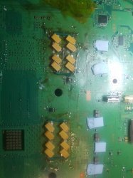
  1. large Heatsinks with heatpipes. Split design, with RSX HS not in contact with CPU HS. Prevents one from heating the other.
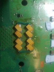
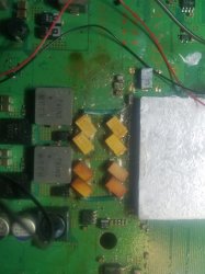
  2. Thermal VIAs between the processor and tokins
  3. Thick ground plane to distribute and sink heat away from hot components.
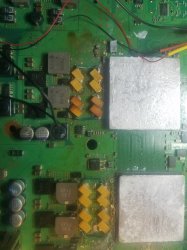
  4. Thermal pads and RF shield to sink hot MB components.
  5. Airflow design that pulls air in through the front, over the RF shield, acting as a heatsink for MB components incontact with thermal pads, and through the PSU, before it contacts the Heatsink fins to dump the processors heat out the back.
The thermal design was carefully thought out. The tokins lifespan was taken into consideration, the thermal VIAs prove it. They provide thermal separation between the processors and tokins, to extend their 2000 hour rating at 105C to a more reasonable number.

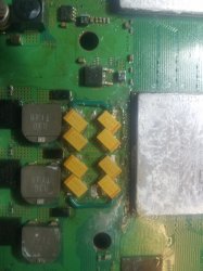
I put a thermocouple between the CPU tokins and measured it at about 65C. But that console had delidded CPU/GPUs, fresh paste, clean fan and case. As the console gets dusty and the paste ages, more heat will be dumped into the board. So I figured my estimate for the operational temps being 65C - 85C.

This is my theory why toshiba laptops had tokin failures. They placed them directly under the CPU! The hottest possable place on the MB. Their operational lifespan inside a laptop, directly underneath a CPU that's soldered to the board, will be much higher than the PS3. It depends on OEM temperature limits, but often laptops allow 100C. That's getting dangerously close to that 2000 hr rating!

Combine that with how most people use devices (never blowing out the HS or periodically changing paste), and you have a recipe for premature failure. Problem is that it also led to the idea that the tokins were defective, which isn't true!

After SONY moved on to AlPol caps in the slims they removed the thermal vias. AlPol caps have the same concern as do the tokins. Their lifespan is dramatically reduced by heat. So they decided that the cooler 40nm RSX and 45 m Cell produced so much less heat that they didn't need thermal separation between them. I don't understand why they didn't include the vias. It would extend their life. I don't think it saves money, or maybe it does at that scale IDK. Point is SONY was playing the balancing game of needed reliability with cost.

They also reduced the size of the heatsinks, removed the expensive heatpipes, adjusted fan curves, designed a more direct airflow path through the console, etc.

There are things we can do to further cool the tokins, to help prevent their failure and the need to replace them. We can add a thermal pad to contact the RF shield. The resin case on to tokins actually insulates them, making them hotter, but you can "delid" it without harming them. Then placing a thermal pad on them in so they contact the RF shield will dramatically reduce their temp. Even a small reduction in operational temps will greatly increase their lifespan. In theory...

I have not tried or thoroughly tested this idea.
 
Back
Top