PS3 (Research/Experimental) - NEC/TOKIN Capacitors Replacement - YLOD

Haha, yeah, @vyktormvmpay25 just ran into that with @mathieulh console. I edited my Frankenstein Mod Tutorial to make a disclaimer that there's a minimum FW revision required to replace with 65nm and 40nm RSX. @mathieulh says the 65nm should work with FW2.30+ and 40nm with 3.40+. If you have FW lower than that and attempt to Frankie them it results in a GLOD requiring a HW flasher to recover from. Or FSM jig, but that's dangerous if you're not sure the FW is 3.55 or lower.
I consider rsx lower fw support wold be on sur board but that may have 21 E8 40 nm code. Now I'm thinking what is lower fw when rsx 40nm with 21 EC was out? Jtp or jsd? Can remember that. Do I consider this right?
 
Thank you for the advice!. I've only applied pressure over the whole IHS of the RSX, which allowed me to boot the console beyond the 3 beeps, but then it would shutdown iteself because of the CELL temperatures getting too high (which is true, as the CELL didn't had the heatsink on and it would be very hot to the touch). If I could get the CELL cool long enough for the console to boot, then I might get a chance.

I'll try to get a heatgun for a reflow, and if I fail then I'll try to sell the parts.
I joined together some images to show you, the image at bottom is something i already made for other stuff (there is a mistake in the RX and TX channel names though, ignore the names) and the image at top was made by kiaw, but note how i mirrored and rotated it to match with the image at bottom
You should use the original image (at huge size) also rotated and mirrored if you are interested in checking other specific pads
RSX-SKEMA-copy.jpg

But one of the first things you should do is to try the pressure tests in the FlexIO, is that border of the RSX i painted in blue... are like 7 channels with 18 lines or so each

And btw... in this pressure tests you should have the motherboard "nude", and with some kind of "rubber" block at bottom with a size similar to the component you are pressing
Lets say... if you want to press RSX you need something at bottom of the size of a cigarrete packet (but solid) perfectly aligned with the vertical of the point you are going to press
The goal of this is to dont bend or wrap the motherboard when pressing it... you know... is needed to do a good amount of pressure but the motherboard should stay completly flat while pressing it
 
While waiting for the capacitors to arrive to fix my PS3 slim (CECH-2004B), I've retrieve the output of the syscon errlogs of another PS3. Let me share with you the info:
  • PS3 model: COK-001
  • Errlogs in External mode:
Code:
PS3 FAT: COK-001 - Syscon errlogs:
=========================
00000000 A0213013 28AFE221 -> BE_SPI DI/DO ERROR
00000000 A0202120 28AFE221 -> HDMI Error
00000000 A0213013 28AFE21A -> BE_SPI DI/DO ERROR
00000000 A0202120 28AFE21A -> HDMI Error
00000000 A0213013 28AFE218 -> BE_SPI DI/DO ERROR
00000000 A0202120 28AFE218 -> HDMI Error
00000000 A0202120 28AFE217 -> HDMI Error
00000000 FFFFFFFF 28AFE217

According to the Errlog codes, this has a dead CPU. No internal modifications were applied to this console prior to me connecting to the syscon, so no deliding or reballing here; but the previous owner told me that he used the towel and hair dryer method to temporarily ressuscitate the PS3 several times some years ago, unaware of the internal damage that he might be causing.

Should I spend time trying to bring this one back to life or should I give up?
 
Yes, thank you for the image, I confirm that I got it right :D. In the beginning that's what I was trying to attemp, got a squared wood block beneath the RSX position of the motherboard and then applied force over the whole IHS. I didn't try to apply force on the FlexIO pins, too afraid of breaking the BGA solder in the opposite side (like a seesaw).

I still need to get a heatgun and was thinking in getting a C clamp too. That way I can have my hands free and avoid some dangerous movements that happen while applying pressure force.
Yeah, a wood block is nice, you can place a mouse pad on top of it (like rubber) to prevent damaging some component by the wood block, those tiny resistors can be riped off easily. This allows to do a lot of pressure safelly

Btw, if the pressure doesnt makes any difference in the FlexIO border of the RSX try in the other border of the RSX labeled as "BA" and "1"... those are connected with HDMI and DVE chips for video outputs
 
While waiting for the capacitors to arrive to fix my PS3 slim (CECH-2004B), I've retrieve the output of the syscon errlogs of another PS3. Let me share with you the info:
  • PS3 model: COK-001
  • Errlogs in External mode:
Code:
PS3 FAT: COK-001 - Syscon errlogs:
=========================
00000000 A0213013 28AFE221 -> BE_SPI DI/DO ERROR
00000000 A0202120 28AFE221 -> HDMI Error
00000000 A0213013 28AFE21A -> BE_SPI DI/DO ERROR
00000000 A0202120 28AFE21A -> HDMI Error
00000000 A0213013 28AFE218 -> BE_SPI DI/DO ERROR
00000000 A0202120 28AFE218 -> HDMI Error
00000000 A0202120 28AFE217 -> HDMI Error
00000000 FFFFFFFF 28AFE217

According to the Errlog codes, this has a dead CPU. No internal modifications were applied to this console prior to me connecting to the syscon, so no deliding or reballing here; but the previous owner told me that he used the towel and hair dryer method to temporarily ressuscitate the PS3 several times some years ago, unaware of the internal damage that he might be causing.

Should I spend time trying to bring this one back to life or should I give up?

I've been able to also output the bringup and becount from this COK-001, hope these are useful:
  • bringup output:
Code:
>$ bringup
bringup
[SSM] state: 0000 -> 0101
Bringup Mode #0 (0xFF)
[SSM] ssmCb_OnStartingBePowOn() called.
[SSM] First Boot.
[SSM] Bringup mode : syspm_stat=00000000/00000000
[POWSEQ] PowerSeq_Setup called.
[SSM] state: 0101 -> 0201
[POWSEQ] AV Backend Setup
[SSM] state: 0201 -> 0102
[SSM] state: 0102 -> 0302
[SSM] PowSeq Fail : Detected !
[SSM] state: 0302 -> 0700
[POWSEQ] AV Backend Letup
[SSM] Shutdown mode : syspm_stat=00000000/00000000
[ERROR]: 0xa0202120
[ERROR]: 0xa0202120
[ERROR]: 0xa0202120
[ERROR]: 0xa0202120
[ERROR]: 0xa0202120
[ERROR]: 0xa0202120
[ERROR]: 0xa0202120
  • becode output:
Code:
>$ becount
[ERROR]: 0xa0202120
[ERROR]: 0xa0202120
[ERROR]: 0xa0202120
[ERROR]: 0xa0213013
[POWSEQ] PowerSeq_Letup called.
[SSM] state: 0700 -> 0600
(PowerOff State) (Fatal)
becount
Bringup : 1422 times
Shutdown: 1350 times
Power-on: 110day 19hour 48min 37sec
[mullion]$
 
Most likely, yes. But it could also be corrupt NAND/NOR, dead HDD, or HDMI transmitter. The last 2 are easy to rule out. Just remove HDD and it'll tell you to insert one. Switching th AV cables should display via analog if HDMI were out. I assume you've tried both of those tho.

So that should leave just the FW or RSX.

You could try a pressure test. Pressing down on the leaf springs over the the RSX to see if that helps (not likely). Could still be the BGA/Bumps if that doesn't work, but confirms it if it does.

You could also measure resistance of the following voltage lines. GLOD can be caused by dead VRAM (FBVDDQ).
mb_ohm_test_points-jpg.36295
Hi there. Sorry for so late reply I was busy with exams. So, I have done the HHD thing but the problem persists. I tried checking these resistances but my board is quite different from yours. But i did find another pic on this forum which was a bit similar so my readings were almost identical to that. But I have found one new thing here. That is the inductor(I presume) near the cell broadband have very high resistance. Which i think is bad for an inductor. There is a pic for reference.

P.S. sorry for the bad image quality.
85bf9e612ef5212760e4879e4aa83d25.jpg
52b200b714915fb7d88a50cf872ca8c6.jpg
 
I've been able to also output the bringup and becount from this COK-001, hope these are useful:
  • bringup output:
Code:
>$ bringup
bringup
[SSM] state: 0000 -> 0101
Bringup Mode #0 (0xFF)
[SSM] ssmCb_OnStartingBePowOn() called.
[SSM] First Boot.
[SSM] Bringup mode : syspm_stat=00000000/00000000
[POWSEQ] PowerSeq_Setup called.
[SSM] state: 0101 -> 0201
[POWSEQ] AV Backend Setup
[SSM] state: 0201 -> 0102
[SSM] state: 0102 -> 0302
[SSM] PowSeq Fail : Detected !
[SSM] state: 0302 -> 0700
[POWSEQ] AV Backend Letup
[SSM] Shutdown mode : syspm_stat=00000000/00000000
[ERROR]: 0xa0202120
[ERROR]: 0xa0202120
[ERROR]: 0xa0202120
[ERROR]: 0xa0202120
[ERROR]: 0xa0202120
[ERROR]: 0xa0202120
[ERROR]: 0xa0202120
  • becode output:
Code:
>$ becount
[ERROR]: 0xa0202120
[ERROR]: 0xa0202120
[ERROR]: 0xa0202120
[ERROR]: 0xa0213013
[POWSEQ] PowerSeq_Letup called.
[SSM] state: 0700 -> 0600
(PowerOff State) (Fatal)
becount
Bringup : 1422 times
Shutdown: 1350 times
Power-on: 110day 19hour 48min 37sec
[mullion]$
You have an error we have seen before. 10x 2120 and 1x 3013 per event. @TwelveAtNight on page 179 had this error and found F6302 was blown and C6320 was short. @patricksouza472 on page 25 of the SYSCON thread had this error combo and found F6302 was blown and C6320 was short. Same thing! That's your best case scenario.

Most of the other times we've seen this combo were in consoles with delid damage or were heat gunned down in their prime. One occurred when the CPU interposer was literally cracked in half from prying force used to try and delid it!

Do you have any service history on the console? Does it look like it's been opened, or worked on previously?
 
@Naked_Snake1995
thanks for your detail compilation of this tutorial, instead of 4x 330uF, i have an ideas of perhaps 2x 680uf cap, do you think it could work? I have seen 6x 470uf and 3x 470uf, but I have not seen 2x 680uf so far, the NEC/tokin is 1200uf. so 2x 680uf might works.
 
You have an error we have seen before. 10x 2120 and 1x 3013 per event. @TwelveAtNight on page 179 had this error and found F6302 was blown and C6320 was short. @patricksouza472 on page 25 of the SYSCON thread had this error combo and found F6302 was blown and C6320 was short. Same thing! That's your best case scenario.

Most of the other times we've seen this combo were in consoles with delid damage or were heat gunned down in their prime. One occurred when the CPU interposer was literally cracked in half from prying force used to try and delid it!

Do you have any service history on the console? Does it look like it's been opened, or worked on previously?
Hi @RIP-Felix, thanks again for the reply! I've checked F6302 and it's definetely blown, no conductivity between its ends; regarding C6320, I'm not able to find it, I've been looking for the Side A diagram on the web but can't find it. Would you be so kind to point me where this capacitor is or to a high-res PDF version of the schematics?

Meanwhile I've probed the capacitors near the MOSFETS (I'm unable to attach a URL, forum keeps telling me that the content of the post has some spam-like or unappropriate content). Image reference is the one on the Power Control Topology - Part 3 post in page 121, top right section of the mainboard:
  • Upper cluster (the one labeled as +1.7v_MISC):
    • The 2 brown upper capacitors give me values of around 42Ohm
    • The 2 black upper 470 e6OF capacitors seem shorted!
      • Multimeter beeps on continuity mode and reads values of 16Ohm on each one of them. Is any one of these the C6320 capacitor?
      • Could it be that the capacitors are fine and the short is coming from somewhere else?
  • Lower cluster (the one under the +1.8v_RSX_FBVDDDQ label):
    • The 2 brown lower capacitors give me values of around 5.45kOhm
    • The 2 black lower 470 e6OF capacitors seem fine. Multimeter doesn't beep on continuity mode and reads values of 83Ohm on each one of them
Regarding the service history of this machine, the only thing I know i what I already told you on my previous post. I can guarantee that yesterday I was the first one to remove the warranty sticker from this console:
According to the Errlog codes, this has a dead CPU. No internal modifications were applied to this console prior to me connecting to the syscon, so no deliding or reballing here; but the previous owner told me that he used the towel and hair dryer method to temporarily ressuscitate the PS3 several times some years ago, unaware of the internal damage that he might be causing.
Should I spend time trying to bring this one back to life or should I give up?
Hope this helps!
 
Last edited:
PS3 #1 - Felix's First Post...Aww
(...continued from SHUMPS forum.)​

I apologize in advance, this is going to be a long post:

The TL;DR:

  • Anyone who says this is a 100% fix is wrong.
  • Reballing is not a con.
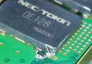
  • The NEC/TOKINs do fail.
  • Low ESR of Tantalum caps matters.
  • The current across the caps is no joke. More jumpers = safer.
  • Total capacatitanc might mater, but dosen't "appear" to.
  • Learn to properly Delid your CPU, make a tool, and do it before you turn your PS3 on again!!!
  • Jailbreak and install webMAN for tighter fan control.
I have been investigating this repair myself for over a year. You can read about my adventure here. I am a hobbyist, not an electrical engineer! However, I have been diving deep into EE videos and technical documentation to try and understand what is really going on. To summarize my findings and experience:

PS3 #1 (CECHA01) has been through hell and is currently dead with a hard YLOD. However, before that the tant cap fix worked multiple times, and failed quickly afterwards due to various soldering mistakes (cold solder joints, not enough jumpers, flux/jumper wires causing bridging, not deliding the CPU IHS which was overheating and complicating things, etc.) In the process I learned how to solder properly to the motherboard and about the RLC circuit the NEC/TOKIN caps are part of.
  • From carefully reading the schematic, this is an RLC power filter/decoupling circuit designed to provide derippled, decoupled, a clean +1.0v (CPU) and +1.2v (RSX). Here is a simplified schematic I made to make it easier to read, but it's not 100% accurate.
    KtnSTNe.jpg
  • The general rule is that using more capacitance if fine (as most of us have been assuming is the case). However, in RLC circuits the capacitance is important if you want to Pass or Stop a specific band (frequency range). Therefore it's possible that SONY engineers chose 4800uF for a reason. The RLC filter is needed because of the DC-DC switching voltage regulators that step the +12v main to 1-1.2v the chips drink. These regulators introduce noise that must be removed. It's most efficient to do so as close to the chip as possible, which explains the proximity of the NEC/TOKIN and the ceramics (CE in the pic above) to the chips. The RLC circuit SONY chose to employ does this very efficiently, but because of the inductor, it introduces resonance. Basically, capacitance could be important. I have not confirmed if the resonant frequency obtained by using 4800uF capacitance is important or not, and not sure how to. However, to remove the variable it is advisable to just match a replacement spec for spec.
  • The amount of current that flows across these caps is large. I found this out the hard way (see pic below). A single AWG22 solid core conductor was inadequate and shorted! I also had trouble with shorting when they laid flat, because they ran over the GND rails. They would heat up, carbonize and short. So I had to go over the top, such that it was impossible to short. Keep this in mind. Below are pics from PS3#1, which didn't survive all the failed attempts and shorts.
eMjhWdy.jpg

9dzAhbc.jpg

37Ts10z.jpg

  • Something odd happened with PS3#1 above after all these repair attempts. The YLOD disappeared! Great, but artifacting would freeze the console within a few minutes of startup. That indicated an RSX issue that probably requires reball to fix. I attempted a reflow and it resulted in a GLOD! I attempted it again with more heat and proper flux, but the board warped on me and resulted in a hard YLOD. I intend to try a reflow and/or reball of both the CPU and RSX, but given how much the board warped, I doubt PS3#1 will survive. I'm still waiting on supplies and may revist it later, but my focus shifted to PS3#2.
    O1mI87K.jpg
PS3 #1 Continued here...

PS3 #2 (A01)
  • ESR is an important consideration in filter circuits. The lower the better. 4x NEC/TOKINs have a combined ESR of 0.375mOhms, so that's the target you should be looking to match. I found that 18x 270uF, 2.5v, 6mOhm Tantalum capacitors have the same total capacitance and a lower ESR. Therefore they are ideal for a CECHA01 as 1:1 replacement. I also chose these for their size, so that they are easier to solder in place, look clean, and can have the OG thermal tape replaced afterwards. I used hot air (380C) in my left hand to preheat the area while soldering the caps in using my iron (340C) in the right. I found it easier to use Kapton tape to hold the Cap in place. I installed 8x of these in place of one NEC/TOKIN for each the CPU and RSX on PS3 #2 (CECHA01), which was a hard YLOD. This console had not been previously worked on and appeared to be stock inside. I decided to leave 3x NEC/TOKINs in place, so I would not need to add jumpers. I delided the CPU/RSX and applied MX-4 TC. This fixed the YLOD and has been very stable about 24 hours of on-time. I jail broke it so I could install webMAN mod and see the temps (67C CPU, 58C RSX, Fan 33%, set point 68C). It's well controlled now and I'm confident that it's going to last, but that remains to be seen.
fgJGRtR.jpg

YlmHSkG.jpg


  • Please note that the total capacitance that fixed PS3#2 is not known because I left the OG caps in place. 2160uF of added capacitance was adequate for this console, but if I were to replace all the NEC/TOKINs I'd have used 18 total per chip to match the OG spec. I didn't need to and adding jumpers is potentially problematic. Many people have has success going over 4800uF total capacitance, so it "apparently" doesn't matter.
  • Lastly, you can't uses continuity buzzer to check your work. The normial resistance between +/GND rails is below the threshhold for most multimeters. I have measured it between 2.5-3.5ohms when the caps are properly installed. Be sure to thoroughly clean the area of flux after install, as I have noticed flux residues can decrease that resistance and cause a short.
I want to offer a hypothesis about the YLOD progression, based off my experience and that of others I've read:
  1. After 2 years, SONY's cheap thermal grease begins to dry. An air gap forms in-between the IHS and the Die on the CPU and/or RSX. Since this is under the heat spreader, it's not easy to get to. Most people do not replace it. People usually only replace the thermal compound between the IHS and the Heatsink, but that's only half of the solution. It's helps lower temps, but doesn't prevent overheating. BOTH CPU and RSX need to be delided!
  2. You start to notice the fan gets noisier. The SYSCON will pretty much allow the CPU/RSX to get to about 75C before the fan ramps into high gear. Above 70C is bad, so SONY's default fan control scheme is terrible. They obviously prioritized sound over longevity. The only way to change this is to Jailbreak the PS3. And it needs to be done. But if you don't change the thermal paste to restore thermal contact between the IHS and the die, then the chips overheat and the fan tries it's best to remove the heat. Of course this is a loosing battle because the chip is becoming increasingly insulated. I noticed this on my working PS3. After a few minutes the fan would ramp up to a noisy level. It still worked, so I assumed it was just the Hot running PS3 we all know and love. But that's not it. It's your fair warning of overheating! I delided the RSX, because it was easy, and not the CPU, because it was hard. I just delided it this week and the thermal greases was completely dried up. There was no direct contact anymore! This needs to be replace on every PS3 that hasn't had it done!
  3. The excess heat places unnecessary strain on the NEC/TOKINs causing them to fail faster. They die and cause a YLOD. Or thermal cycling at temperatures above 75C places unnecessary stress on the BGA and causes fatigue fractures leading to a YLOD, before the Caps fail. Based on two consoles I've personally replace caps on, which is too small a sample size to draw definitive conclusions, I would say that the caps fail first more often.
  4. People send their console in for a reball, which repairs the BGA. If the cause of the YLOD was the caps, the heat from the process often restore function to the NEC/TOKINS temporarily before they die again. This could explain some of the reballed consoles that YLOD again within a matter of months. Some repair shops don't remove the IHS during the reball. First this means it takes longer for them to heat up and be removed, which is harder on the chips and motherboard. Second, they did not fix what was causing the chips too overheat in the first place. So they will again overheat and cause another YLOD soon after the reball. Lastly, the heat that shorten the life of the NEC/TOKINS may not have killed them before the solder balls cracked and caused the YLOD. A reball my fix the console and it will run until the NEC/TOKINS finally die (which they are prone to anyway). This accounts for the rest.
  5. Fed up, people sell their PS3 cheap on e-bay.
  6. We install a tantalum caps to repair the consoles that do not have damaged solder balls. Deliding is still necessary to prevent excess heat and thermal stress that would eventually cause BGA damage. Combining these with a reball may provide a longer lasting repair, but placing that much heat on chips will shorten their life. So a reball should be avoided. The best way is to delid and cool the chips as soon as temps start to rise out of control. And a jailbreak with webMAN mod to monitor temps and tighten up the fan controls will help immensely.
PS3 #2 Continued here...

18x 270uF, 2.5v, 6mOhm Tantalum capacitors this is thing that I have been looking for. finally gotten it, thanks for your nice writeup.
 
Hi all,
First thanks for this topic, as I found it when looking for informations regarding deliding CPU and RSX of my CECHB00.

Unfortunately, I kind of sliced the plastic case of a NEC Tokin cap when deliding IHS of CPU.
My question is: what the risk for hardware if I boot the PS3 after assembling it back?
When looking at internals of a NEC Tokin cap picture taken by wrx884 in the quoted message below, it looks like mine is not damaged because only the corner of the cap case was sliced.
Here's a picture of the damaged cap:


Just for reference heres a photo of some burnt Tokins from a recent console i just completed and sent back to its owner and FINALLY got one under my belt (1 of 13) and got one to work using new tant caps.

Heres the original Owners post @SeanRanklin so u can follow his own issues and the repair

https://www.psx-place.com/threads/cecha00-60gb-ps3-shuts-off-in-only-one-game-ylod-style.20826/

Long story short with the GPU side replaced the console still shut down during game play, it wasnt until the CPU side was done also when results were seen and Games could now be completed with no shut downs at all.


View attachment 25921

View attachment 25919
 
Hi all,
First thanks for this topic, as I found it when looking for informations regarding deliding CPU and RSX of my CECHB00.

Unfortunately, I kind of sliced the plastic case of a NEC Tokin cap when deliding IHS of CPU.
My question is: what the risk for hardware if I boot the PS3 after assembling it back?
When looking at internals of a NEC Tokin cap picture taken by wrx884 in the quoted message below, it looks like mine is not damaged because only the corner of the cap case was sliced.
Here's a picture of the damaged cap:
I think there is no problem, but i would seal it with some glue to prevent the air to enter inside it
It have some metal sheets inside made with special materials or chemicals... i guess that sheets could be oxidized
 
Hi again!
I've managed to boot into the xmb menu of my CECH-2004B by temporarily solder a 440uF tantalum cap as @Pacorretaco suggested in page 178 before removing the original TOKIN. I then wanted to access via syscon UART connection to some diagnostic info but as the syscon tutorial implies, that's not possible. Is there any way to extract info from syscon via the python script now or must I install the PS3 Advanced tools? The console isn'jailbroken yet.
 
I think there is no problem, but i would seal it with some glue to prevent the air to enter inside it
It have some metal sheets inside made with special materials or chemicals... i guess that sheets could be oxidized
Thank you very much!
I put everything back together and the console could boot.
Temps seem fine, I need to see on the long run.
 
Hi, thanks for providing such an amazing method to fix YLOD for phat ps3 consoles.

But I got an issue, so register a new account to ask.

After reading carefully, I just have confidence to make it done since I got some soldering exp by glitching xbox360 previously.

I followed all the procedure but stuck here: cleanup the mass after "physically" removing old tokin capacitor by knife and tweezers.

I'm using my old friend -- a 80w goot solder iron, just serving quite a long time, and I don't think it has some problem at all.

But for some MYTH reason, it DOES NOT melt the remaining solder ANY MORE!

When I try to add some new solder to it for luck, it DOES NOT help but only adding more waster solder to it.

Of course I have used flux (quite a lot may I say? and it should be working fine as I used it these days for other purpose), NO help.

Afterwards borrow the hot air gun from my friend, and adjust to 450C and 50% air flow to blow it for 3-5 mins, it DOES NOT melt any more solder. ( I must admit I'm not good at using this since it's the first time )

BTW using desoldering braid DOES NOT help, stick instantly if I try to.

I just wonder if my solder iron or the hot air gun screwed or something. Then try to use these tools to blow some components on a waste board. They ALL worked perfectly. ( I guess could be the solder points are not as big as ps3's)

CECHA00(jap version) if you may ask the model. Board model is COK-001.

How am I supposed to cleanup all this big piece of sh*t on the board? Can I just connect some capacitors in parallel? (Desoldering is useless, so I guess soldering is quite possible for now)

I'm tired with it. I doubt this is made by some future technology.
The problem is the ground "stripe" of the tokins is connected with a big copper layer, it have VIAS (holes) connecting with another big copper layer at the other side of the motherboard, and probably it have also more internal copper layers connected to the VIAS too
Is like a big piece of metal... and the effect is pretty much like if you try to solder in a big piece of metal... lets say the tip of your solder iron is at 200ºC but by touching the metal with it is only heated upto 150ºC (the other 50ºC are lost all along the metal material, is acting as a heatspreader)

In a hot air gun there is also a temperature leak because the 450ºC you mentioned is meassured at a resistance located inside of the gun... but the temperature of the air decreases with the distance... in the practise is imposible to transfer 100% of the heat, there is always some amount of it lost

So... the solution is to overcalculate the temperatures, in other words... you need more heat
I would try to start warming up the tokins with the hot air gun, and when you think is ready use the solder iron without removing the hot air... this way you are combining the heat of both tools

Btw, the factory solder is lead-free (it requires higher melting temperatures), so is a good idea to add new leaded solder (that should alloy with the lead-free) and then remove it as much as posible, either with a solder pump of desolder braid, i know is tricky but whatever that works... the goal is to remove as much as posible of the lead-free solder... or better said... to replace the factory lead-free solder by leaded solder... and remember, the flux helps a lot to reduce the melting point and improves the alloy, ab/use of the flux a lot
Thanks for you reply.
I will follow your suggestion to have another try afterwards.
 
How am I supposed to cleanup all this big piece of sh*t on the board?

Low melt alloys, preheat the board, better soldering station.

Stations with the heating element in the handle can not recover heat quickly enough when they are held to a giant copper plane. Stations that use cartridge style tips (heating element in the tip itself) have gotten ridiculously affordable in the last few years. Look up TS100 or Pinecil for cheap/portable options, or Sugon A9 245 (a JBC clone that can even use their tips) for a real station.
 
Last edited:
Back
Top