PS3 Syscon fan settings (Coordinate Graphs)

Ok but did you try my settings?
Because that was my idea too...
You just have to copy and paste, then say if they are crazy or not and help improve them if necessary or come up with alternatives.

For me step 0 is writing the modified settings. It is the first thing I do after getting access to internal commands...

Even if the board is still not working, I do it then in 1 go and then I can rest easy. The first time the thing boots, will already be protected even if it has no heatsink on

And dont forget everything is harmless, tested and fully reversible if you change your mind for some reason. Nothing is set in stone... And it is hard to make it worse than original...
Yes, paco. I started with yours when I first started doing this. They're the template I've been tweaking for the 40nm RSX and etc. You're right, it's as easy as copy/pasting the code into the CMD terminal and checking the last checksum is correct before hitting enter. I just adjust the parameters in the code first, try the changes to see if I like than and try again if not.

I wasn't referring to your curve as hap-hazzard. I was saying the approach we take in general should not be haphazard. That we should respect the exponential ramp up of the Tupper, because that rate of change is calibrated to respond correctly to heat increases. Not to be too fast or slow. The actual fan percentage or temperature can be changed, we just have to make sure the rest of the temps are adjusted acordingly to result in that exponential shape, without flattening it. In that scenario the temps could run away too quickly and cause the fans to jump several fan% before "catching the heat" and bringing them back under control. We want fan% to rise in a controlled fashion, so that sudden changes in load can't raise the temps suddenly. That creates a wider thermal swing and reduces BGA reliability.

Ideally we would tighten the Upper and lower thresholds to keep the temps in a narrow window, so that the temps stay +/- 1-2C from a setpoint. Like how webMAN works. That will prevent the BGA from flexing as much as possible. But doing that causes the fan % to swing/down all the time. It's great for reliability, but annoying AF.

I could make a SYSCON Fan curve that mimics that function for enthusiasts that want webMAN like control, but don't want to jailbreak. And a separate one that balances fan noise with temps, for those who find it annoying. I'll experiment and see what I can come up with.

Once I receive the "Franken-miracle" 65nm from @Computer Booter I'll have 3 consoles I can develop fan curves for.
  • 90nm COK-001
  • 65nm COK-001
  • 40nm COK-001
They should be applicable to COK-00X models. Probably not SEM, since it has a different fan. But the BC models are the ones I, and I think most people, are interested in. Screw the non-BC models. They're a dime a dozen. If they fail, just buy a new one. That may be insensitive of me, but...I don't care. I have 2 slims (one of which I gave my dad), both 2001A models with tokins. They still work fine. The only mod I did was to drill holes above the fan for more direct air intake. My dad's been using his primarily as a Bluray player and for his music library. So it mostly idles. But he never dusts it and I have to do it when I visit. I believe I changed the thermal paste to MX-4, but that was so long ago I can't remember doing it.

I honestly don't worry about slims.
 
I understand the wish to use a "formula" to try to do it "right" but to be honest I think they used a formula just to be lazy, not to do it right.

Even if that is looking much better now,
If you use any "formula" like that, you are treating all the phases as if they were the same, when in reality there are fundamental differences between them.
For example, warmup phases should not be following the same "rules" as operating phases or panic phases.
The math formulas i mentioned are intended to create the curve for "rsx tempU" automatically in the same way is made in the official thermal configs of most PS3 models, i think the engineers started by doing this first and for us is handy to start like that too when we are designing a thermal config from scratch
When talking about this im constantly imagining how it would look represented in a coordinate graph and what i said only applyes to the vertical arrows, note i have not mentioed the speeds at all so im not defining the control points of the curve... that control points are defined later when you intersect the vertical lines (for temps) with the horizontal lines (for speeds)
Note also the math formulas i mentioned applyes to all PS3 models because im generating all the "rsx tempU" values derivated from the "rsx tshutdown", i insisted in mentioning that most people is going to agree in not exceeding 85ºC because the resulting values of the math formulas are going to satisfy everybody
I was talking about it months ago (the first time i realized about this trick) but it was a bit controversial :D
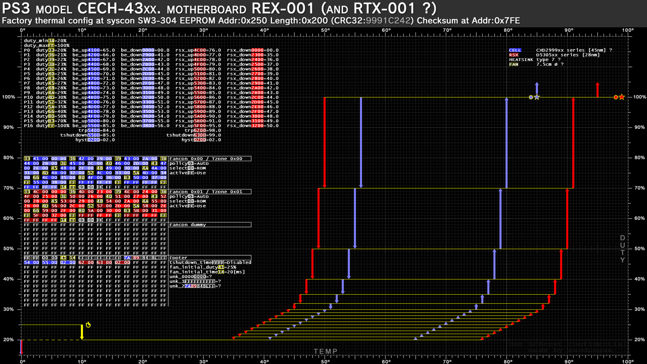
, the fact is we can make a custom thermal config compatible with all PS3 models, of course not adjusted accuratelly to the hardware but good enought because the syscon is smart enought to select a proper speed, and is not going to allow any overheat, the worst thing that couold happen by using a generic thermal config is the fan could become too much sensitive (many annoying fan speed changes) under the "full workload" region, but even that effect can be prevented by extending the values of "tempD" a lot to the left
Anyway, im not suggesting to use a generic thermal config 100% build using math formulas, my explanation was just the easyer way to start designing it when you are confronted with a paper+pencil+eraser with an empty graph and you need to start painting in it. One of the images i uploaded was intended to be printed for that purpose btw, i think is the best way to play around with it :D

What i suggested about "cloning" the other curves is just an addon... i just mentioned it as curiosity sake, but the fact is they can be cloned only partially, there are 4 or 5 (lets say optional, because the engineers was not doing always the same) deviations that we still need to discuss later
As example... at top speeds they are moving the values of "tempD" to the right because they doesnt wants the PS3 to stay using the "defcon speeds" for much time... thats another "sony engineers favourite rule" easy to copy, i like it (and i would abuse of it) but i didnt mentioned it when i was talking about the math formulas because is a bit advanced... lets say... thats chapter 2 of the book :D

In the same way, I dont think it is a good idea to change or remove the 20% initial warmup speed. Because is just there to be the first speed the user hears when they press the power button. It doesn't need to be high, is just for the first minute or so.
Again... im thinking in all this visually :)
By moving the horizontal line at most bottom a bit up we can move also the other lines on top of it a bit up too. In some cases is mandatory to move the others because in the original config the horizontal lines at most bottom are so close to each others that if you move one of them you really need to move the others too
Basically... we are displacing the horizontal lines to an area that is more important

The time lenght the lowest speed is going to be used depends of how you intersect the horizontal lines with the vertical lines... im not mentioning the vertical lines here but everythign depends of that intersection
You said that speed is used only for 1 minute or so... well, if we are wasting a bullet in something that is going to be used only 1 minute i consider is a waste
The good thing is to extend the time this speed is used... by moving the horizontal line up... so the speed is faster and you can use it 3 or 5 minutes instead of 1 minute

In any case I think this chat probably belongs more in the modification thread because I am beginning to see that people are missing some explanations there and therefore making some wrong judgements of this complex stuff.
Well, this thread is intended to talk about thermal configs too, about the official thermal configs mostly and that "sony engineers favourite rules" they used, there are still many things i would like to discusss related with that rules, lets say, im focusing this thread mostly to the theory behind them, and your thread fits well to publish custom configs and to discuss that custom configs
 
Last edited:
My approach is going to be this.

  1. Delid IHS' and apply MX-5
  2. Burn in the paste with 2 hr test. Then let it cool and settle overnight. I always get about 1C lower temps the next day.
  3. Use default SYSCON Fan to Record idle temps and fan% in XBM after the console has reached thermal soak (15 mins or so)
  4. Use default SYSCON Fan to record Highest temps and Fan% in a demanding game like GTA5.
  5. Choose a temperature I would like to keep the CELL at in XMB. Say 65-68C. Then enable webman at that setpoint and allow it to reach equalibrium. Record the Fan%.
  6. Repeat step 5, but for temps in game with a setpoint based on the highest fan% I can stand. So I adjust the in game setpoint until the temps are as close to the XMB setpoint they can be without going over the fan% I find unbearable (44%, but depends on fan model and bearing condition)
  7. Once I know what my desired idle XMB and max stress Fan%'s are supposed to be, I can then calibrate SONY's curve to my numbers witout changing the shape of the curve. The rate of change, not the temps or fan%. Those will change to suit my needs, but how quickly they ramp up will stay the same because I'm keeping the exponential curve. I'm just shifting it down. Sorry if the Math(s) is(are) anoying, but this is a practical application and reason you should pay attention in school.
  8. Tlower is just going to be a matter of listening to the console and adjusting it to keep it from ramping up/down too much.
I'm not trying to make an enthusiast fan curve. Not for best possable performance. I'm trying to make a ballanced curve that acomplishes the same goals SONY was after, to appeal to the wider audiance of people that hate being distracted by the noise. I'm just turning the insanity down from bat $h!t crazy to "ok, I can live with that."
I was talking about temperature tests here https://www.psx-place.com/threads/ps3-superslim-temperature.36841/
In the idle test you need to stay idle as many time is needed for the temperatures to stabilize completly. In other words, the point where the temperatures stops increasing
If you are picky with this idle test you need to wait lot more than 15 minutes (is mostly around 30 or 45 minutes), because in this first warmup from ambient is needed to heat all the PS3 parts, included metal pieces, the plastic shell, etc...
Is heat that cumulates very slowly but there is a point where everything becomes stable
Anyway, there is no need to extend the idle test much time because is just a prelude to the second test ingame at full workload :)

Try to keep a record of the difference of temperatures in between CELL and RSX (and the timings when the temperarure samples are taken), this is going to give you a very important indication of which one is hotter at different points
Your PS3 is a bit special, but in a reatail PS3 (not frankenized), in the first minutes when starting from ambient you should have the CELL hotter than RSX... later they stabilizes... and later ingame the RSX should be the hottest
With that info (a bit orientative, dont take it literally) you can adjust the difference of temperatures inside the thermal config for "cell tempu" and "rsx temp u" at different ranges
In other words... by modifying the shape of the curves you can adjust the sensitivity of "who drives the car" at different workload ranges

The 2 speeds you mentioned (your favorite in idle, and your favority ingame, found by using webman) probably needs to be surrounded by a couple of speeds close to them, to soften the noise levels generated by the fan speed transitions a bit in that range (the psicological placebo effect you mentioned some posts ago, is good to use it in the areas that matters)
 
Last edited:
sandungas said:
In the idle test you need to stay idle as many time is needed for the temperatures to stabilize completly. In other words, the point where the temperatures stops increasing
If you are picky with this idle test you need to wait lot more than 15 minutes (is mostly around 30 or 45 minutes), because in this first warmup from ambient is needed to heat all the PS3 parts, included metal pieces, the plastic shell, etc...
Is heat that cumulates very slowly but there is a point where everything becomes stable...
This is what I mean by "heat soak." Like being soaked with water where you cant get any more wet, heat soak is when the console is as hot as it's going to get at that fan%.
 
The 2 speeds you mentioned (your favorite in idle, and your favority ingame, found by using webman) probably needs to be surrounded by a couple of speeds close to them, to soften the noise levels generated by the fan speed transitions a bit in that range (the psicological placebo effect you mentioned some posts ago, is good to use it in the areas that matters)
Yeah, you get my meaning now.

Idle and ingame temps are going to be the widest plateaus, where the fan% doesn't change much. I just need to decide what fan% will keep the console cool at said loads, without bumping too far down or into the next higher level. It may require 2-3 levels, like SONY needed to acomplish the same thing.
 
This is what I mean by "heat soak." Like being soaked with water where you cant get any more wet, heat soak is when the console is as hot as it's going to get at that fan%.
Ok, first time i did read your post i tryed to translate it but google translator was not doing a good translation of the word soak :D
Yeah, is like a saturation of heat, btw there is a myth that worths to be mentioned, some people thinks that playing a long session of 8 hours is a lot worst than a session of 2 hours, well, thats not completly true because if we meassure the max temperatures for the whole sessions the result is going to be the same
Is because the PS3 reaches that point of temperature soak after 1 hour or so... or well maybe 2 hours but not much

For some reason some people thinks the PS3 cummulates heat infinitelly, gaming sessions of 1 hours are fine, 8 hours are dangerous, and if you keep gaming for 24 hours it explodes :eek:

Yeah, you get my meaning now.

Idle and ingame temps are going to be the widest plateaus, where the fan% doesn't change much. I just need to decide what fan% will keep the console cool at said loads, without bumping too far down or into the next higher level. It may require 2-3 levels, like SONY needed to acomplish the same thing.
And we need to keep in mind we are configuring it for different ambient temperatures (winter or summer), the performance of the thermal paste is going to decrease along time (in the next years until you replace it), also is good to have a fallback just incase "shit happens"
Is like a dual sided sword... the most accuratelly you adjust it for your current enviroment is the worst that it can be adapted to a different enviroment... so you need to adjust it a bit rough on purpose

Let me show you why i think 10 speeds are scarce and needs to be used wiselly, im going to use the 45% speed you mentioned that you consider annoying
c1.jpg

This 3 lines are the "defcon" speeds i been mentioning before, the speed at 100% is a must do, the speed at 45% is just because you mentioned it but you could increase it a bit more to 50% or whatever, and the speed i added at 75% is just because you dont want to jump from 45% to the 100% in a single step, that would be an annoyance and is not convenient because one of the purposes of this defcon speeds is to work as an acoustic alarm... you know... very easy to recognize when playing incase are triggered, is nice to have 2 or 3 of this acoustic alarms justincase
c2.jpg

Here im adding the line for the minimal speed, 20% from factory, but if you increase it a bit more (in other words, if you move the horizontal line a bit up) you are reducing the distance in between it and the other lines so is going to be easyer to "fill the gaps" in between 20% and 45% when we add more speeds later, also allows to keep the minimal speed for "p0" step for a few more time
c3.jpg

Now i added 2 blue lines for your 2 favorite speeds in idle and ingame... i dont know the exact speed so i just spreaded them evenly in between 20% and 45%
c4.jpg

In the thermal configs that supports up to 20 speeds you can dedicate a lot of speeds to the intermediate points to smooth the speed transitions... but in your config you only have 4 remaining speeds, so you need to do somethig like this
There are many ways to do this, i just added 4 red lines surrounding the blue lines a bit roughly

EDIT:
btw, yesterday i figured a little hack to increase in +2 the total number of speeds for all PS3 models, is not tested though, if someone have a guinea pig PS3 for the experiment let me know, is needed to modify all the values of temperatures and speeds
There is another little hack to increase the total number of speeds in +1 by repurposing the values named "initial fan duty" and "initial fan time"
 
Last edited:
This is mostly a sample of the new style, if some of you have some suggestion this is a good timing to mention it
Syscon-fantbl-settings-v47-copy.png

I made lot of changes, but just to mention some of the most importants...
The vertical scale (for speeds) starts in 10% and ends in 120% to maximize the space available for the texts, i had to rebuild the grid (2 times) but at the end i took the most radical solution because with the actual style there is room to display the texts for up to 20 speeds (the "p" steps)... this covers the maximun number of speeds availables to use in superslim PS3 models
The font height is maximixed to fit in that area, is in bold and have beed streched to cover the maximun space available (common for all the graphs of all retail PS3 models)
In the initial style of this graphs i was displaying all the texts in black font... later i changed the background to black and i was using "font highlights" effects, but that was a pita (it took many time to highlight the characters individually). Now all the texts are in white font... and the "highlights" is a layer at bottom completly independant from the texts that represents the "thermal config format". In this image the highlights belongs to "thermal config format v3", common for all sherwood syscons
The color highlights are exactly the same used in the samples from https://www.psdevwiki.com/ps3/Syscon_Thermal_Configs#Thermal_Config_Formats (this was tricky, is something i was thinking many time ago but i was not sure if i was going to be able to achieve, i like it a lot)
One of the goals when designing an style for this graphs was to make all them to match in the positions of the texts and the hexeditor view... at some point i went into problems (when vyktor shared the thermal config from one of the superslims) because there was an overlapping, but now is solved, all them are going to have the texts and the hexeditor view located exactly in the same position
Additionally... the new scale (bigger than 100% speed) allows me to add the vertical arrows that goes under 0% and over 100% speeds missing in the previous versions of my graphs (i know is weird, but they needs to be represented that way... i will talk about it later, there is a hack related with them :P)
Im also representing the "tshutdown" temperatures with a star... yeah is like an explosion :P
I added a yellow icon with a timer for the "fan_initial_duty" and "fan_initial_time"... i hope this is a bit more intuitive
All the value names are official "codenames" taken from the syscon firmware dumps
All the values with a lenght of 2 bytes are temperatures (except "tshutdown_time")
All the values with a lenght of 1 byte and yellow color are related to duty (except "fan_initial_time")
Now im mentioning the syscon model in the title, in general the title has been improved and im still wondering if assing some colors to it (blue/white sony style)
Im adding some info related with the CELL/RSX/SB models at top-right corner... but im not sure how much to add and how to do it
 
I been doing some more changes :)
Syscon-fantbl-settings-v48-copy.png


For curiosity sake... this graph (and the graph for NPX-001 that is almost identical, only differs in 2 bytes) was the reason why i had to rebuild all them, note how close are the values of "rsx_down" to the longest vertical red arrow... the font size and font effects of the texts in the graphs for all the other motherboards is adjusted to that arrow :D
In the other thermal configs that monitors the southbridge... doesnt exist this problem of posible overlapping with the vertical arrows so i will add another 2 more text columns for temperatures of "sb_up" and "sb_down"

The most important change is that i moved the "duty_max" text row after the highest "duty" value (in other words... after the highest "p" step), i was thinking in it before but i was not sure if it was going to be a pain to do it (and it is but i will do it anyway)
In my oppinion is more intuitive becuse usually the value of the lowest "duty" matches with "duty_min" (and the value of the highest "duty" matches with "duty_max"). Also it creates an small "gap" in beteen the values of temperatures "up" with the other group of 3 temperatures for "trp", "tshutdown", "hyst", it looks a bit more clear

The other detail is that i "closed" the hexview at the bottom with a horizontal line, and i added the text "Thermal Config Format v3"... because that layout of the image with the text background color highlights is common for all the sherwood syscons, and all them are going to display that text with "Thermal Config Format v3"... the only difference in between them is the total number of speeds (the "p" steps")... there are thermal configs from format v3 with 14, 15, 16, 17 speeds
Right now i have all the graphs ready with this new style for all the retail PS3 models with sherwood syscons (superslims, slims, and the last fat VER-001) because are sharing this style of "Thermal Config Format v3"

The next thing i have to do is to create the layout with the background highlights for "Thermal Config Format v1" (the COK-001 motherboards with the additional info for SouthBridge) and i hope everything will fit well
As you can see i started with the superslims because are easyer (there is less info to display) ;)

EDIT:
Just to be clear... as explained in wiki there are 3 thermal config formats https://www.psdevwiki.com/ps3/Syscon_Thermal_Configs#Thermal_Config_Formats
Im keeping my graphs synced with the info published in wiki in many ways... as you can see the "color code" is the same, btw remember you can increase the font size of your web browser by keeping the CTRL key pressed and moving your mouse whell (incase you want to zoom in/out in wiki)
thermal-config-format-wiki-screenshot.jpg


I made the thermal configs for v3 (the easyests)... and now i should do v1 (the hardest)... im leaving v2 for the ending because is something intermediate and will be easy after checking everything fits in v1
 
Last edited:
This is mostly a sample of the new style, if some of you have some suggestion this is a good timing to mention it
Syscon-fantbl-settings-v47-copy.png

I made lot of changes, but just to mention some of the most importants...
The vertical scale (for speeds) starts in 10% and ends in 120% to maximize the space available for the texts, i had to rebuild the grid (2 times) but at the end i took the most radical solution because with the actual style there is room to display the texts for up to 20 speeds (the "p" steps)... this covers the maximun number of speeds availables to use in superslim PS3 models
The font height is maximixed to fit in that area, is in bold and have beed streched to cover the maximun space available (common for all the graphs of all retail PS3 models)
In the initial style of this graphs i was displaying all the texts in black font... later i changed the background to black and i was using "font highlights" effects, but that was a pita (it took many time to highlight the characters individually). Now all the texts are in white font... and the "highlights" is a layer at bottom completly independant from the texts that represents the "thermal config format". In this image the highlights belongs to "thermal config format v3", common for all sherwood syscons
The color highlights are exactly the same used in the samples from https://www.psdevwiki.com/ps3/Syscon_Thermal_Configs#Thermal_Config_Formats (this was tricky, is something i was thinking many time ago but i was not sure if i was going to be able to achieve, i like it a lot)
One of the goals when designing an style for this graphs was to make all them to match in the positions of the texts and the hexeditor view... at some point i went into problems (when vyktor shared the thermal config from one of the superslims) because there was an overlapping, but now is solved, all them are going to have the texts and the hexeditor view located exactly in the same position
Additionally... the new scale (bigger than 100% speed) allows me to add the vertical arrows that goes under 0% and over 100% speeds missing in the previous versions of my graphs (i know is weird, but they needs to be represented that way... i will talk about it later, there is a hack related with them :P)
Im also representing the "tshutdown" temperatures with a star... yeah is like an explosion :P
I added a yellow icon with a timer for the "fan_initial_duty" and "fan_initial_time"... i hope this is a bit more intuitive
All the value names are official "codenames" taken from the syscon firmware dumps
All the values with a lenght of 2 bytes are temperatures (except "tshutdown_time")
All the values with a lenght of 1 byte and yellow color are related to duty (except "fan_initial_time")
Now im mentioning the syscon model in the title, in general the title has been improved and im still wondering if assing some colors to it (blue/white sony style)
Im adding some info related with the CELL/RSX/SB models at top-right corner... but im not sure how much to add and how to do it
Looks nice, great job.
Though if you are looking for suggestions, I have some minor ones.

Simply the vertical scale, Is only a visual thing but I feel it shouldnt necessarily be linear, because most of the useful infofrmation is being squished to a very small area.
The area between 20% and 40% should take most of the screen, because they are the most important, while speeds over 40% are the "panic" ones. These speeds are not so relevant (user shouldnt even get to see them in the real world) but in a linear scale, they take most of the screen...
Also you were concerned about having a limited number of speeds or "phases" and well, I think even 9 are enough but if need more, these are the ones to delete to have more.
In my fan curves I removed one of the "panic" levels to move it into the operational area. You could remove more I think, without losing anything important. Panic is panic, no need so many steps in the panic haha. Precisely because is not a linear thing.

Maybe this goes a bit into the fundamental idea of "subdividing" the speeds. Warmup speeds, Operational speeds and panic speeds. Could be also represented in the vertical scale, maybe with a gradient or something.

And last tiny visual suggestion is the TempU and TempD arrows in the chart. Especially the TempD arrows coming down instead of up is a nice touch, but could go further and make them different color to differentiate better at first glance. Darker shade of red or blue, or even dotted lines or something.

Finally, would be good to make the templates easy to edit for example people that make custom fan curves, could make their chart following this design too, for easy comparisons

Cheers
 
Maybe this goes a bit into the fundamental idea of "subdividing" the speeds. Warmup speeds, Operational speeds and panic speeds. Could be also represented in the vertical scale, maybe with a gradient or something.
I like this idea, i will see if it fits well some kind of subtle color degrade at the grid at back
Actually, the previous versions of the graphs had a partial black degrade at left to remove some of the grey lines from the grid background (to dont disturb the texts), but im not sure if i disabled them temporally for this latst tests... i need to check that too :D
And last tiny visual suggestion is the TempU and TempD arrows in the chart. Especially the TempD arrows coming down instead of up is a nice touch, but could go further and make them different color to differentiate better at first glance. Darker shade of red or blue, or even dotted lines or something.
I thought in it but i leave the idea appart, mostly because it would mean to redraw half of the vertical arrows in all the graphs.. but yeah... maybe i will do it later (after solving the big problems, thats would be an extra)
Finally, would be good to make the templates easy to edit for example people that make custom fan curves, could make their chart following this design too, for easy comparisons
In the initial versions i made one in white (intended to print it in real paper and draw on top of it with a pencil)... you know it really needs to be white background because we dont want to waste a ton of black ink from the printer... and because all pen/pencils are dark colors :D
I need to do this version of the graph "empty" in white background for printing... my plan is to leave only the graph and invert all colors... by now i have not made experiments with this but most probably i will need to adjust some black tones to keep control of the grey tones that are going to generate after the inversion
Additionally... if you want yeah... i could make another one "empty" with the black background im using... this is mostly intended to use it in graphic image editors (gimp, photoshop, whatever)

The main problem with this "generic" templates if the amount of lines at most top depends of the total number of speeds... to make them generic i need to cover up to 20 "p" steps, this way
This is the layer im using as reference... all the grey rectangles are text characters ▇


Syscon-fantbl-settings-v48-ref-copy.jpg
 
OMG @ElGris i just realized the last 2 motherboards where you connected the UART adapter contains a thermal config labeled as "unknown" by now
https://www.psx-place.com/threads/p...d-or-even-spin-discs.37596/page-3#post-339974
Finished :)

RTX - 001 NOR -> CokR10
PPX - 001 NOR -> CokP20

Is mentioned here, only 2 thermal configs missing in the collection
https://www.psdevwiki.com/ps3/Syscon_Thermal_Configs#Missing_thermal_configs
*Needs confirmation:
**PPX-001 (probaly identical to the thermal config found in PQX-001)
**RTX-001 (probaly identical to the thermal config found in REX-001)

The theory is...
PPX-001 and PQX-001 uses pretty much identical components... so in theory the they should share the thermal config too
RTX-001 and REX-001 uses pretty much identical components... so in theory the they should share the thermal config too
But nobody provided a sample of the thermal configs from PPX-001 and RTX-001 so we dont really know... and as a consequence of this i was adding his names with question marks in my graphs

So i need you to check it, the easy way is to use the python script to do a dump of the "readable" syscon areas (a file with size 5KB)
After that you need either share the dumps or check it yourself, i trust your word, so you can check it yourself and simply tell me "yes, it matches" and that would be enought :encouragement:

If you use HxD you just need to open the dump in it, and use the option in the tabs named
edit---> selet block... with values 0x250 (start offset) and 0x200 (lenght)
After that use the option analisys ---> checksums and click in the CRC32

As you can see in the wiki page sections is mentioned the CRC32 of every "thermal config", in theory...
PPX-001 <--- CRC32 = 8E7F2A49
RTX-001 <--- CEC32 = 9991C242


---------------
EDIT
As example, this is one of the last images i made, note how im adding the name PPX-001 at top in between brackets and with question marks, this sucks a bit, and the only reason why i was doing it is because im not completly sure in the thermal config of the graphs belongs to PPX-001 too :crybaby:
Syscon-fantbl-settings-v48-copy.png
 
Last edited:
So i need you to check it, the easy way is to use the python script to do a dump of the "readable" syscon areas (a file with size 5KB)
After that you need either share the dumps or check it yourself, i trust your word, so you can check it yourself and simply tell me "yes, it matches"
I don't even know how to do this haha. I was going to use de command "r 0 7" and I saw this post of you.
 
I don't even know how to do this haha. I was going to use de command "r 0 7" and I saw this post of you.
Open this wiki page, with the mouse highlight all the code inside the frame "SysconEEPdumpSW.py" and copy it
https://www.psdevwiki.com/ps3/Talk:SC_Communication#Example_Scripts
Then create a "New Text File.txt" in your PC, paste the code in it, and rename it to SysconEEPdumpSW.py
Thats the python scrypt you need to run

And you need to run it inmediatly after doing the "auth" (in the way you are doing it)
You know... first you are using an script to authenticate with syscon... and after that you are running the ">r 0 7" command... but instead of running the "r" command you need to run the script, and the script will run a bunch of commands for you automatically and will create a file of size 5KB

If you open that file in a hexeditor you will see it starts with the "Cok" name... and the "thermal config" is located at 0x250
 
Hello.Tell me how to take the team to set up the fan? on COK-002 to be like on cok-001 CECHB
Hmmm, im not sure what you are asking for, but it doesnt makes much sense to use the thermal config from COK-001 in a COK-002

But before talking about it, let me show you something, in this page we have been collecting some official thermal configs, but eventually we had a conflict of thermal config versions because there was people reporting different configs for the same motherboard model, there are also thermal configs that was found in different motherboard models
To try to keep some control of this mess we are using the eepcsum (a syscon command), or the CRC32 checksum (easy to calculate in PC) as an unique identifyer of every config
https://www.psdevwiki.com/ps3/Syscon_Thermal_Configs

Long story short...
CRC32: CA0A6A87 (eepcsum: EADE) <----------- this one was found in a COK-001 only (it seems it was an early japanese unit, and probably produced in a japan factory)
CRC32: 79BA37D0 (eepcsum: 7115) <------------ this one was found in a COK-001 and COK-002
As a bonus... this thermal config is also compatible
CRC32: F0899A5E (eepcsum: 0E17) <------------- found in COOKIE-13 prototype

Both are compatibles with each other, in theory can be swapped, but the one with eepcsum: 7115 is better, so only makes sense to "upgrade" from the thermal config EADE to 7115 (not the other way around)
And only makes sense if you really really want to keep a 100% official config made by sony engineers (in other words, if you are afraid of "breaking" it with custom settings)

Before taking that decission the first thing you need is to identify the thermal config of your COK-002...if you have the UART 2 USB and you are able to run syscon commands you just need to run the "eepcsum" command and syscon is going to show you either EADE or 7115
Right now you are not sure which one you have in your COK-002

Anyway... the official thermal configs are not so good, all them can be improved, if you are not sure what to do with them i suggest to use the settings configured by someone else for your motherboard, @Pacorretaco and @RIP-Felix shared some custom configs for COK motherboards here
https://www.psx-place.com/threads/modifying-syscon-fan-settings-better-than-webman.34626/
 
Last edited:
fantbl setini 0 p0 00.00 74.00 0x33
fantbl setini 0 p1 60.00 75.00 0x40
fantbl setini 0 p2 61.00 76.00 0x48
fantbl setini 0 p3 67.00 77.00 0x4d
fantbl setini 0 p4 68.00 78.00 0x5a
fantbl setini 0 p5 71.00 79.00 0x66
fantbl setini 0 p6 71.50 80.00 0x73
fantbl setini 0 p7 72.00 81.00 0x80
fantbl setini 0 p8 72.50 82.00 0x99
fantbl setini 0 p9 73.00 85.00 0xff
tshutdown setini 0 85
fantbl setini 1 p0 00.00 83.00 0x33
fantbl setini 1 p1 48.00 84.00 0x40
fantbl setini 1 p2 71.00 85.00 0x48
fantbl setini 1 p3 77.00 86.00 0x4d
fantbl setini 1 p4 78.00 87.00 0x5a
fantbl setini 1 p5 80.00 88.00 0x66
fantbl setini 1 p6 80.50 89.00 0x73
fantbl setini 1 p7 81.00 90.00 0x80
fantbl setini 1 p8 81.50 91.00 0x99
fantbl setini 1 p9 82.00 95.00 0xff
tshutdown setini 1 95
r 34fe 2Just like that to carry the data? and another question, cok-001 was installed rsx 40 nm outputs a voltage of 1.0 volts, need to be redone to 0.95?
 
fantbl setini 0 p0 00.00 74.00 0x33
fantbl setini 0 p1 60.00 75.00 0x40
fantbl setini 0 p2 61.00 76.00 0x48
fantbl setini 0 p3 67.00 77.00 0x4d
fantbl setini 0 p4 68.00 78.00 0x5a
fantbl setini 0 p5 71.00 79.00 0x66
fantbl setini 0 p6 71.50 80.00 0x73
fantbl setini 0 p7 72.00 81.00 0x80
fantbl setini 0 p8 72.50 82.00 0x99
fantbl setini 0 p9 73.00 85.00 0xff
tshutdown setini 0 85
fantbl setini 1 p0 00.00 83.00 0x33
fantbl setini 1 p1 48.00 84.00 0x40
fantbl setini 1 p2 71.00 85.00 0x48
fantbl setini 1 p3 77.00 86.00 0x4d
fantbl setini 1 p4 78.00 87.00 0x5a
fantbl setini 1 p5 80.00 88.00 0x66
fantbl setini 1 p6 80.50 89.00 0x73
fantbl setini 1 p7 81.00 90.00 0x80
fantbl setini 1 p8 81.50 91.00 0x99
fantbl setini 1 p9 82.00 95.00 0xff
tshutdown setini 1 95
r 34fe 2Just like that to carry the data?
Please put some effort in your posts, we have a language handicap because none of us are native english speakers :D
Im not sure what you mean with that values, if you copyed them from some of the samples published by other people they should be ok i guess, but i cant make a "review" of them to tell you how much i like (or hate) them, this takes some time and at this point im too much used to represent them in a graph before making any conclusion
You could take the "clean" image (without lines) in the first post of this thread and paint your settings in it to have a better overview

--------
Yes, if you run the eepcsum command syscon is going to show you a list of checksums, in mullion syscons (the syscons soldered by BGA) is going to tell:
checksum at address 34fe should be XXXX

Thats the thermal config identifyer... after modifying the thermal config you need to update the value XXXX (to match with the new thermal config). Basically... you need to write at position 34fe the value displayed by the syscon eepcsum command

and another question, cok-001 was installed rsx 40 nm outputs a voltage of 1.0 volts, need to be redone to 0.95?
Im not sure at that details, but my personal oppinion is that i like that voltage reduction for the PS3 fat frankensteins with 40nm RSX
 
Something interesting from the TMP411 datasheet that is easy to understand, probably some of you already realized about some of the things im going to say because are intuitive, but there are a couple of details that are not so intuitive, also this is a proof of how syscon deals with the temperature values

If you keep attention at the temperature values that appears inside the "thermal config" syscon region you are going to notice that ALL the temperatures (not only the "tempU" and "tempD" inside the fan tables, but also the "trp", "tshutdown", "hyst") are represented by a value of 2 bytes lenght... and it needs to be converted to celsius degress. But that conversion is a bit special

We need to split the value in 2 individual bytes, the first byte (named "temperature register high byte" in the datasheet) is a straightforward conversion in between hexadecimal and decimal, the thermal monitor chip allows the temperatures to be configured in 2 different formats (to cover 2 different ranges of temperatures), and it seems in the PS3 are configured as "standard binary" format (in other words, they can meassure a range from 0ºC up to 127ºC)
After converted to decimal this byte is a ronded number, as example
0x05 = 5ºC
0x0A = 10ºC
Etc... as can be seen in this image (the column at left for "standard binary" format)
0l3CoH3.jpg


The second byte (named "temperature register low byte" in the datasheet) represents the decimals of celsius degrees and is not so straightforward
At this point is needed to mention that the thermal monitor chip allows to monitor 2 thermal sensors, one is inside the chip itself (named "local") and the other is external (named "remote"). From the table below we dont care about the values conversions of the "local" because it seems to be disabled in PS3 (the circuit is designed to monitor the sensors inside CELL/RSX that are considered "remote" by the thermal monitor chip)
So... we only care about the values at left in this table, for the remote, that is using a resolution of 0.0625ºC (think in this value as the precission, thats the minimal fraction of temperature the PS3 can meassure)
esjkTKm.jpg


Now taking this to the practise...
In the official thermal configs you are going to see many times the temperature is represented with values like:
0x4B 0x80 = 75.5ºC

The second byte with value 0x80 is used a lot in the official thermal configs, this means they was always using a precission of 0.5C (half a celsius degree), and they does it when the temperature is increasing at the lower fan speeds... you know they was trying to soften a bit that noise level changes in the first initial minutes after the PS3 is booted
In my oppinion if you are creating a custom thermal config is not needed to use decimals because i dont care if the first fan speed changes happens with a notable difference in the noise level
But... if you want to configure it with decimals (mostly in the slims and superslims that allows to use up to 20 fan speeds, so you have some fan speeds to waste at the lower values) i suggest to dont go with a lot of resolution because is overkill, the highest precissions are the kind of feature that it was not needed for the PS3, but well... the texas instruments chp had that feature and sony just acepted that design

If you are creating a custom thermal config and you want to work with a precission of 0.5ºC there are only 2 posibles values (like in the official thermal configs)
0x00 = 0.0ºC
0x80 = 0.5ºC
And if you want to work with a precission of 0.25ºC there are only 4 posibles values
0x00 = 0.00ºC
0x40 = 0.25ºC
0x80 = 0.50ºC
0xC0 = 0.75ºC

Thats more than enought in my oppinion
Hey @sundungas I am having the A801200 on a pqx-001 motherboard and am thinking about replacing the tmp411A (The cell temp sensor and yes I tried sys on diag and looked-up the thermal error) so is there anything else I should keep in mind before replacing both rsx and cell tmp411A and B.
Any other circuit to test any surrounding components to replace
PQX is a SS. IIRC aren't thoses IHS soldered to the die? Usually the issue is related to overheating because of the need for a delid, but if it's soldered that shouldn't be the case. Perhaps it is the thermal monitors as you suggest. Or the internal diode, in which case RIP.
 
PQX is a SS. IIRC aren't thoses IHS soldered to the die? Usually the issue is related to overheating because of the need for a delid, but if it's soldered that shouldn't be the case. Perhaps it is the thermal monitors as you suggest. Or the internal diode, in which case RIP.
Yes pqx is superslim cech4200a series.
Not ihs related its soldered and probaly the tmp441a related cause just before it died I repasted it with a cheap hy650 something paste 10 tens before it died no stress games other than ps2 classic that I delete because of artifacting and a couple of low end psn games no artifacts on them.So I am taking the tmp11a as entity of interest here also coming back to my inquiry what's other things should I measure to replacing it and what other components should I replace other the both rex and cells tmp411a and tmp411b.
@RIP-Felix you can help with my case feel free to check to my previous posts.
 

Similar threads

Back
Top