Thats what i was thinking while reading the last posts of the thread, he mentioned also that they could overheat
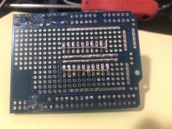
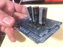
Is pretty much the same i was suggesting in this thread, using a "stripe" of electrolytic capacitors
https://www.psx-place.com/threads/ps3-cechk01-from-ylod-to-glod-to-shutdown.29428/
That "stripe" i suggested is working as a single capacitor.. if we reduce it to the minimal we just need 1 capacitor of 4800uf for CELL and another capacitor of 4800uf for RSX (this calculation is for the tokins rated as 1200uf)
And for the other tokins used in newer PS3 models rated 1000uf the total capacitance needs to be 4000uf each
Edit:
And btw, another of the tests made by squeept is he removed half of the capacitors (so at that point he had a total capacitance of 2400uf for CELL and another 2400uf for RSX)... and the PS3 was working and he was able to play gran turismo... is just the game crashed at some point because he was at the limits, and this was an extreme test, lol
But this gets us an idea of how much margin we have to reduce the total capacitance values... im not sugesting to reduce it so much... but you know... instead of the 4800uf from factory probably there is no problem in reducing it down to... lets say... 4500uf
This reduction should not be specially problematic, is just is going to make them a bit more prone to failure caused by wear in the long run
In plain words... reducing the total capacitance a bit could be worthy because using less capacitors simplifyes the work
Actually, that ones with 4700uf are very close to the factory 4800uf
")

")