PS3 (Research/Experimental) - NEC/TOKIN Capacitors Replacement - YLOD

I am very happy that you help me.

At the end of the day I'll try to check the capacitors. However, I will have to solder short wires because it is possible that such a large capacitor will not fit in the holes in the upper metal plate.

I never paid attention to voltage capacitors. It is possible that it does matter. I have always made sure that the value is higher than the voltage circuit used.

Keep fingers crossed. I hope the console starts :dejection:
 
time for conclusions ...
I tried to fix YLOD with new 4700uF 6.3V and 2200uF 6.3V capacitors.
I tried different combinations:
-capacitor 4700uf on RSX on the cable
-capacitor 4700uf on RSX directly
- 2200uf condenser on RSX on cable and directly
-2x 4700uf capacitor on RSX on cable and directly

I was combining RSX and CPU simultaneously ...
(black 4700uF ; green 2200uF)
The result - always YLOD. Only times ranged from immediate to three seconds.

On the CPU I had to mount the capacitor on the cable due to difficult access.

I have no strength :(


glad to see success in this project! I shelved mine for a year+ now after initial failure and it is about time for me to revisit this. still need to read through the whole thread.

Was my original concern ever answered? https://i.imgur.com/gkCx4GC.png?2 for some reason my board only had continuity between the pads listed in my photo above before caps were ever soldered. is this normal, or do I have a short somewhere before caps were even soldered?

also from solder job pictures ive seen it appears like scraping the solder mask on the 'middle ground' vias to get ground is viable? is this the best method? this excites me if true because I definitely scraped and bridged a few of these during removal of the NECs. if this is truly the route to go the picture I see sent around by @Workz_777 with the kapton tape seems nice for 'straight' cap soldering avoiding doing it diagonally
 
Your lines are wrong.
Upper lines and bottom lines are positive
Middle lines are negative.

Στάλθηκε από το POCOPHONE F1 μου χρησιμοποιώντας Tapatalk
 
yea thats what is concerning me. before the cap replacement i foolishly used a heatgun on the cpu and gpu while pouring liquid flux in... pretty sure i am in need of a proper reball and shorted something if i am not getting correct continuity
 
However, if the water-pressure is too high then it can cause problems in the system.
Great explanation except one thing to me, i noticed. The voltage rating of the cap can be higher and should be (depending on application, and specs required), to not always run at 100% capacity. TV manufacturers get away with this all the time to make your TV break after a small time. Replacing a 2.5v cap with a larger one, say 6.3v shouldn't normally cause any issues, or even with a larger one. The problem then becomes the actual physical footprint.
 
time for conclusions ...
I tried to fix YLOD with new 4700uF 6.3V and 2200uF 6.3V capacitors.
I tried different combinations:
-capacitor 4700uf on RSX on the cable
-capacitor 4700uf on RSX directly
- 2200uf condenser on RSX on cable and directly
-2x 4700uf capacitor on RSX on cable and directly

I was combining RSX and CPU simultaneously ...
(black 4700uF ; green 2200uF)
The result - always YLOD. Only times ranged from immediate to three seconds.

On the CPU I had to mount the capacitor on the cable due to difficult access.

I have no strength :(


I don't have to make any bridges with the original caps?
Since I was interested in the YLOD repair topic, I bought 5 consoles very cheaply. I will use them for testing.

After yesterday's attempts, I was very angry and I used a heat gun - the console works, so it's a 100% capacitor problem.

There are 4 consoles left - I don't know if they were heated in the past.

I currently have no more ideas. Does the capacity have to be equal to the original? What if the capacity is bigger? the console will also be YLOD? Maybe in the presence of original capacitors I have to use smaller capacity?
 
glad to see success in this project! I shelved mine for a year+ now after initial failure and it is about time for me to revisit this. still need to read through the whole thread.

Was my original concern ever answered? https://i.imgur.com/gkCx4GC.png?2 for some reason my board only had continuity between the pads listed in my photo above before caps were ever soldered. is this normal, or do I have a short somewhere before caps were even soldered?

also from solder job pictures ive seen it appears like scraping the solder mask on the 'middle ground' vias to get ground is viable? is this the best method? this excites me if true because I definitely scraped and bridged a few of these during removal of the NECs. if this is truly the route to go the picture I see sent around by @Workz_777 with the kapton tape seems nice for 'straight' cap soldering avoiding doing it diagonally

Hiya, here is a post from Sandungas around this topic, from page 103, also see his comment below.

This is what i meant, i took one of the images posted above and tunned it a bit :)

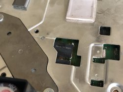
This image could help to see how are connected, and if someone needs it you can use it to draw on top of it, is "clean", i colored the areas of copper ---> https://i.imgur.com/IeTKMbj.jpg
Black = ground
Red = V_IN of the tokins
Orange = V_OUT of the tokins (but also V_IN of CELL/RSX)


As you can see point A and B are connected to each other (and at the other side of the board you have another 2 tokins connected togeter to A and B). Same stuff with C and D
That areas in red and orange colors have the geometry of a rectangle... so if you want to do it simmetrically you can do this with only 1 wire
Note i located the solder points of the wire very close to the VIAS (holes), because that VIAS are what connects one side of the motherboard to the other side of the motherboard... in plain words, im doing it this way because i know that VIAS are the main "river" (are the bottlenecks with the biggest amount of water)... im trying to make a "bypass" in between the bottlenecks
AR1eP91.jpg


This way is correct too following the same rules i mentioned before, because is symmetrical, the amount of "water of the river" is going to be divided in half, in plain words, every wire is going to carry 50% of the water
eyM2C4S.jpg


But remember... you just need to do this bridging only if you remove all the tokins
And you can do it with only 1 wire (use a thick wire)... but you are free do do it with 2 or 3 and in both sides of the motherboard, is fine... but most probably is pointless and could be counterproductive because all that solder peaks are going to cause interferences as mentioned before
You know... the amount of interferences is going to be smaller if you do it with 1 or 2 wires... but if you do it with a lot of wires is wrong

And where Sandungas also says:- "And btw, the images of my previous post could help to understand what happens when you use a multimeter to meassure resistence/continuity in between ground and the points marked as C/D
Some people went confused because they removed the tokins but they still had some continuity in between ground and C/D

As you can see in the image, when you touch C/D with the multimeter (the orange areas) you are really "touching" inside CELL/RSX... so you are meassuring the internal circuits of CELL/RSX :)
 
Last edited:
Great explanation except one thing to me, i noticed. The voltage rating of the cap can be higher and should be (depending on application, and specs required), to not always run at 100% capacity. TV manufacturers get away with this all the time to make your TV break after a small time. Replacing a 2.5v cap with a larger one, say 6.3v shouldn't normally cause any issues, or even with a larger one. The problem then becomes the actual physical footprint.

For sure totally agree, there needs to be a margin beyond what is actually needed, for both Volts & Capacitance. Like how the Ps3's RSX & CELL pull approx 1.2V, and only really need 2400uF of capacitance each to function. But Sony gave them 4800uF & 2.5V. I think Sandungas & Littlebalup were discussing this on maybe page 5,6,7 (soz can't remember exactly) ...that Sony gave much more margin than was needed (say the usual "rule of thumb" 50% margin) and instead gave a 100% margin, so that over time as the caps degraded they would keep functioning.

However, if the RSX, during a spike / surge, tried to pull more than 2.5V, the NEC caps would fail before the RSX would ever see that higher voltage. But if the cap was rated 25V, then it's the RSX that would be damaged first and not the cap, during a spike / surge. And maybe it's easier to replace a failed capacitor (at least with low voltages) than a fried processor.

Also, water pressure / air pressure, is effected by the size of the pipe-work it flows through. If the pressure is too high and the pipes are too small = whistle noise (high frequency). And if the pressure is too low and the pipes are too big = humming noise (low frequency).

So for sure there needs to be a balance. Same with electronics:- Characteristic Impedance / Reflection Noise / Resistance / Reflection by Impedance / Ohmic Conductor, etc.

Anyway, i play alot of Mario games, so i know alot about plumbing :wink::cool2: ...yeahhh.
 
Last edited:
what is best tantanulim capacitors for CECHG01

Hiya, you might want the low-height (1.8mm) Panasonic ones, they fit nice under the metal sheilds.
(470uF - 2.5V)
https://www.mouser.co.uk/ProductDet...2QGsKpvcg6orrXF53s0AeGvzo04E6jM9yambsnJ/xRg==

Alot of people in this thread went with those capacitors, but there are other types, like the AVX ones (yellow), but they are higher and can touch the metal sheilds, also they don't come in 2.5V - they start at 6.3V. There are a few other types also that people used. Different brands, etc.

If you go for branded ones, it can be expensive, and you might want to try with some Chinese clones first, and if you find the capacitors solve your Ps3's issue, then you could always invest in the proper branded capacitors, from the authorized sellers like:- Mouser, Newark, Farnell, Digi-Key, after.

Or before all of that, you could even try a quick & cheap test first with electrolytic capacitor(s) like esc0rtd3w shows 1 page or so ago, with 2 wires (+) and (-) going to a combination of 2x 2200uF - 6.3V (or can do the same with 1x 4700uF - 6.3V). Brands like Rubycon, Nichicon, Panasonic, etc, are good ones.
 
well i got a new CECHB01 yesterday and it had the YLOD removed the NECs with a heatgun on high, added tantalums and it worked but would YLOD when ejecting discs or freeze in PS2 Games, so i had ordered "New" NECs off ebay for the fun of it and i had put new NECs on that ps3 after it wouldnt boot(GLOD style) and eversince i used original NECs it has been perfect no issues and it ran GT6 fine no crashing, and no artifacts it was doing that before, so i will probs use the rest of the NECs i bought since i dont have anymore good tantalums these NECs will prob last a few years, now Delid time!

here is somewhat my work tho, i replaced all the NECs on this side i only have a photo of one of them its quite messy
 

Attachments

  • 214DD6E5-3973-43E8-81B5-571187DC6A56.jpeg
    214DD6E5-3973-43E8-81B5-571187DC6A56.jpeg
    1.5 MB · Views: 588
  • 7A2F4FC1-CE41-429B-A850-D020AB996B3F.jpeg
    7A2F4FC1-CE41-429B-A850-D020AB996B3F.jpeg
    854.1 KB · Views: 158
I don't have to make any bridges with the original caps?
Since I was interested in the YLOD repair topic, I bought 5 consoles very cheaply. I will use them for testing.

After yesterday's attempts, I was very angry and I used a heat gun - the console works, so it's a 100% capacitor problem.

There are 4 consoles left - I don't know if they were heated in the past.

I currently have no more ideas. Does the capacity have to be equal to the original? What if the capacity is bigger? the console will also be YLOD? Maybe in the presence of original capacitors I have to use smaller capacity?

@inazuma-akai well good work bro, at least you tried all the combinations, thanks for the photos.

Can i ask - so the same Ps3 you've been working on, where you tried all these combinations using electrolytic capacitors, the one in the photos, is the same one you then heated with a heat gun, and then it worked?

...if yes, can i ask:- Where did you heat up? What (approx) temperature? For how long?

Also, when you say the Ps3 works, did it boot up as normal, or did it fail soon after?
 
well i got a new CECHB01 yesterday and it had the YLOD removed the NECs with a heatgun on high, added tantalums and it worked but would YLOD when ejecting discs or freeze in PS2 Games, so i had ordered "New" NECs off ebay for the fun of it and i had put new NECs on that ps3 after it wouldnt boot(GLOD style) and eversince i used original NECs it has been perfect no issues and it ran GT6 fine no crashing, so i will probs use the rest of the NECs i bought since i dont have anymore good tantalums these NECs will prob last a few years, now Delid time!

Oh wow! How many NECs did you remove and replace, all of them?

Would you wanna try on your other Ps3s that were problematic with the tans, and put new NECs on them too, just to see?
 
Oh wow! How many NECs did you remove and replace, all of them?

Would you wanna try on your other Ps3s that were problematic with the tans, and put new NECs on them too, just to see?
i did the top 4 NECs the underside of the CPU/GPU side and that worked fine, i have one more B01 i got recently that was artifacting so i will try later probs, my original B01 from last summer is toasted solder bridged on the GPU but i will try my other B01 and report asap!

also that PS3 was on 2.60 and wasn't artifacting it was just extremely laggy and locking up on the XMB, i updated it to 4.86 and thats when it started to artifact
 
Back
Top