PS3 (Research/Experimental) - NEC/TOKIN Capacitors Replacement - YLOD

It works! (After replacing the other top one)

I've been in and out of it so many times thou, thermal paste is crap. Gonna give that another application and see how it does.

UPDATE: CPU still running hot...but it's running. :) w\60% Fan it Idles at 72C.... lil hot for my taste but it seems stable so far.

UPDATE2: Today it's idling at 61C, put a few more screws in it since I'm not gonna be inside it much now that it's working.

698573f2e6a4cc2a6a624da2bf4dae90.png
 

Attachments

  • 20190813_192811.jpg
    20190813_192811.jpg
    167.8 KB · Views: 436
  • 20190813_192815.jpg
    20190813_192815.jpg
    171.4 KB · Views: 466
Last edited:
I was about to mention it, at top in this photo
20190811_225758-jpg.19491


And there is another one about to fall (and get lost) at bottom-left in this photo too
20190811_225756-jpg.19490


At this point i dunno if could be repaired, the scratches doesnt seems to cut any line, but with all that other components around damaged is going to be a pain to imagine how they was located originally, which kind of components they was, his values, if is needed to replace some of them, etc...
Yeah no it's totally toast, didnt realize how much I had damaged. Luckily, the system had only cost me $20...

Fortunately, the one I just got in is a CECHA01, I'm gonna try some other more careful methods this time around, I was a bit too excited to get a better fix than something that would only last a few months.

Any recommendations on how to remove the capacitors? Soldering iron still the best way?
 
Is 6 AM here, and i can't see sh@t [emoji23][emoji23]

Why my pocket knife methods remind me of another horror flick, i am sure @Cypher_CG89 would be the first to watch it on Netflix [emoji23][emoji23]

Sent from my G8141 using Tapatalk

Your funny lad.... I don't watch really Horror films anymore as the modern ones are sh!t compared to the old ones> Nightmare on Elm Street, Friday the 13th, the shining etc. The only new one I remotely liked was the the new IT and even that is crap compared to the old one. Or the Silnet Hill films. Horror directors and writers have no imagination anymore and more or less copy eachother or rip off older films on one way or the other. And the Resident Evil films are more or less just action shoot'em ups but there ok.

Also I hate Netflix ... it's sh!t lol.

I have a horror film for you to watch live..... for free...... " The Mutalation of Snakes BC PS3's....:oie 19113229e8ymug9p:Cypher Strikes Back...." I think you would love to watch that.....:rolling::rolling::rolling:
 
Look at the table posted by @VTSTech here: https://www.psx-place.com/threads/t...eplacement-ylod-fix.25260/page-15#post-198300
2562dedd9bc86b0e7d06b5a33c5a67ec.png

The most convenient are the ones with "size code" = D2E
The voltage in the original tokins is 2.5v, so forget about the others that works at 6.3v
And there is no need to buy the ones with 470uf, the ones with 330uf are enought
So then this would be fine? https://www.mouser.com/ProductDetai...2QGsKpvcg6n3J/lz87fU6nPnGx8n3wb4f6S/qCz5exA==
 
Any recommendations on how to remove the capacitors? Soldering iron still the best way?
Basically, is needed to overheat the area, the problem is that heat is dependant of how many metal is connected to the point you are heating
In general... ground points needs more heat because the ground lines are always big areas of metal
Here also the voltage lines are connected to lot of vias (holes) that tranfers the heat to the other side of the motherboard, and to internal layers (all made with copper)

So yeah... i never did this myself, but just by looking at the images im sure it needs lot of heat, thats the tricky part

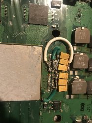
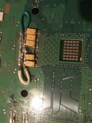
Also, check some of the photos posted by people... it can be seen how some of the tokins was removed before the tin was completly melted... thats very risky because you can lift (or break) a copper trace by pulling from the tokins

*This problem can be identifyed because it can be seen the shape of the tokin in the tin... it means the tin was not completly liquid

You know... the materials have 4 states... liquid, solid, gas and plasma
In betweem them there are intermediate states... like a "semisolid" where the tin is like a paste
If you pull from the tokin when the tin is in "semisolid" state you dont know the results, the only safe way is to pull from it when the tin is completly liquid... but as mentioned before for some of you this is going to be hard to achieve because is needed lot of heat

Tip: If you have 2 solder irons try use both together
Tip2: Add lot of tin (and i mean... a lot) over the factory tin to change his melting point
Tip3: Flux ftw

Yes, is fine
You are buying them in expensive brands and places btw, as i mentioned before (in general) the capacitors are not considered important components, and there is a wide range of values aceptable if need to replace one

As example, you can replace a capacitor that originally was 5v by other with 12v, or a capacitor with 700uf by another with 1000uf... or both things together a capacitor originaly 5v @ 700uf by another with 12v @ 1000uf
Im not sure if there is some exception to that, but i did it with monitors, tv's, PC power supplies and PC procesors, and my experience is that always works

So... the point is... if you already have some capacitors at your home (recycled from other device or because you bought them time ago for other stuff but never used them) then is fine to try with different values (always bigger)
But if you are going to buy them is better to match the factory values

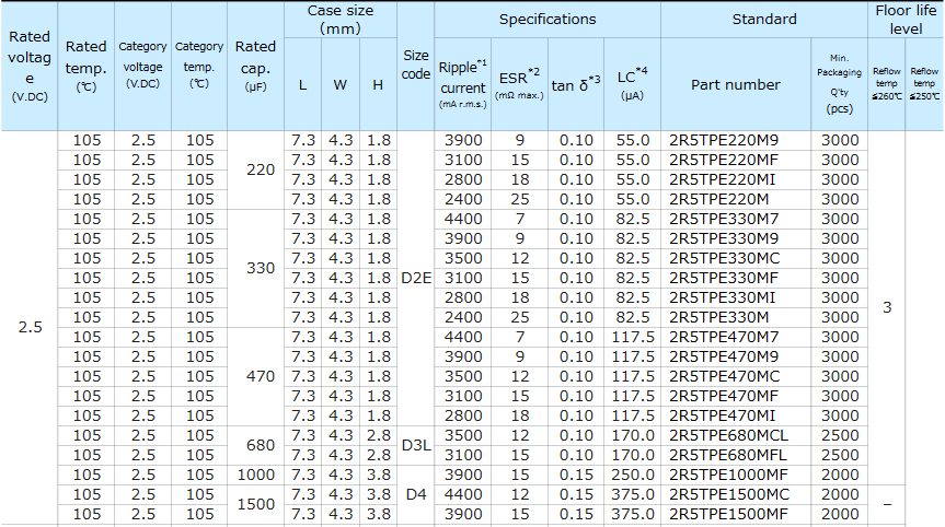
In this case the original voltage of the tokins is 2.5v so if you are going to buy them... yeah there is no doubt, 2.5v wins
About the capacitance... well... in the way you are soldering them (4 tantalums for each tokin) you need to equal or surpass a total capacitance of 1200uf (because this was the original value of everyone of your tokins)... so you can do it with... 330uf * 4 = 1320uf
Thats good enought, actually is a bit over the original 1200uf and thats fine

But if you use 4 * 470uf = 1880uf
Im not telling that doesnt works, we know it works, but is not needed, actually if you really want to use 470uf you can do it with 3 * 470 = 1410uf
This will make the solder job easyer because you only need to solder 3 tantalum capacitors for every tokin... but again is not needed

*Also keep in mind you have 4 tokins connected together for CELL.... and another 4 tokins for RSX, so when doing the calculations we need to multiply by 4 to get the total capacitance, as example, your PS3 from factory was using:
1200uf + 1200uf + 1200uf + 1200uf = 4800uf for CELL
1200uf + 1200uf + 1200uf + 1200uf = 4800uf for RSX

And you was replacing them by:
(4 * 470uf) + (4 * 470uf) + (4 * 470uf) + (4 * 470uf) = 7520uf for CELL
(4 * 470uf) + (4 * 470uf) + (4 * 470uf) + (4 * 470uf) = 7520uf for RSX

See the difference ? is huge 7520 - 4800 = 2720 extra (added by you, but not needed)

In my oppinion the "hotspot" is in 2.5v @ 330uf ...one of the reasons is because are cheapests, to make this repair is needed to buy a bunch of them so this is important
The 2.5v @ 470uf are fine though, all depends of how are you going to solder them... the suggestions made by littlebalup was interesting, there are several available :)
1QJVbTR.jpg
 
Last edited:
Has anyone else been watching YouTube videos watching people replace the Nec/Tokin capacitors on the Toshiba L330 and L730 laptops just to get a feel for what it will look like? Lol probably just me.


Sent from my iPhone using Tapatalk
 
Soooooo....

I screwed up... A bit.
Removed 2 NEC from Cell, 2 from RSX.
The last one I took off I guess I pulled a bit too hard and ripped the tracer off (no metal connection, just white PCB.
20190818_064529.jpg


But I at least had some practise and soldered 6 caps onto the other 2 NEC spaces.

20190818_064536.jpg


I'm wondering now though... As the NECs are wired in parralel, might I be able to solder onto the available tracers and not use the one I ripped off...?

This has made me realise that my soldering skills are pretty poor haha
 
I'm wondering now though... As the NECs are wired in parralel, might I be able to solder onto the available tracers and not use the one I ripped off...?
Yes, it should work, the trace you ripped is the line most at top-right corner in this photo i guess ?
I painted it on top to see that are very big areas... in some of them is needed to scratch the green varnish to expose the copper, but there are a lot of "alternative" solder points
Also, keep in mind if you flip the motherboard, at the other side you have pretty much the same
jd2JsiI.jpg


Have you made some test about heights with the metal shield in his place ?, in the photos it looks the tantalum capacitors are a bit higher (because there was lot of solder in the copper before you started soldering them)
To prevent that is good to use "desoldering braid" (or "desoldering wick", same stuff) to clean up the area before starting soldering
Desoldering-braid.jpg

Im posting a photo of a legit product (is not just copper, it has some powder in between the braid that does some chemical magic)... but you can do this for free at home with normal wires... you know is needed a wire like that, made with lot of thin threads... like the shielding used by the cables for TV antennas or things like that

Edit:
I mean... this kind of cables (typically used in TV antennas) https://en.wikipedia.org/wiki/Coaxial_cable
The external shield (marked as B) is a braid of copper... and is pretty much the same than the "desoldering braid"
If you have a cable like this at home you can use his braid to cleanup solder works... is not as good as the "desoldering braid", but it will work
RG-59.jpg
 
Last edited:
I will not discuss the validity of this process as a repair, like he said everyone will try this at his own responsibility, he will not be liable of any damage or loss, what I wanted to say is that soldering is a skill not everyone has and it takes a lot to learn it , this process involves a lot of desoldering and a lot of soldering, I attached a picture of a motherboard we received from a customer just to show everyone an example of where this can end , this customer did not just lose the money he paid for the soldering iron, the solder, the flux, the solder wick and the capacitors, he also lost his motherboard that he had to buy another replacement for it for $175 so when you try this make sure you understand the cost and all the losses so there will be no regrets at the end. When a YouTube video surfaced more than ten years ago telling people they can fix their PS3 by using flux and heat gun a lot of people went out and bought flux and heat gun and they ended up with a lot of damaged beyond repair consoles, I wouldn't overstate that the number of hear lost consoles was in millions, I don't want this to happen again . Check the picture and good luck everyone that wants to try this.
 

Attachments

  • C569E765-9879-468F-9E55-2D0DFA23D4D2.jpeg
    C569E765-9879-468F-9E55-2D0DFA23D4D2.jpeg
    1.5 MB · Views: 1,676
  • DAEB1158-397C-42B4-8BB7-F3AE14542AD8.jpeg
    DAEB1158-397C-42B4-8BB7-F3AE14542AD8.jpeg
    1.6 MB · Views: 843
Last edited by a moderator:
I will not discuss the validity of this process as a repair, like he said everyone will try this at his own responsibility, he will not be liable of any damage or loss, what I wanted to say is that soldering is a skill not everyone has and it takes a lot to learn it , this process involves a lot of desoldering and a lot of soldering, I attached a picture of a motherboard we received from a customer just to show everyone an example of where this can end , this customer did not just lose the money he paid for the soldering iron, the solder, the flux, the solder wick and the capacitors, he also lost his motherboard that he had to buy another replacement for it for $175 so when you try this make sure you understand the cost and all the losses so there will be no regrets at the end. When a YouTube video surfaced more than ten years ago telling people they can fix their PS3 by using flux and heat gun a lot of people went out and bought flux and heat gun and they ended up with a lot of damaged beyond repair consoles, I wouldn't overstate that the number of hear lost consoles was in millions, I don't want this to happen again . Check the picture and good luck everyone that wants to try this.


My soldering test on dead mobo (always make tests and tests again before to proceed...) :

k1f3wG6.jpg


8Lx143M.jpg


LxSFhW5.jpg


I don't like the way I connected the jumper wire to the capacitors. I'll change that next time.
 
so i replaced my old 470uF 6.3V tantalums with 470uF 2.5v ones on my COK-001 Board. the system sometimes boots at works. i can get it to load up a ps2 iso and it will play fine. then i press the menu button to open the ps2 settings and the system artifacts heavily. i can continue to play the ps2 games (prob since its using HW not SW) then after seeing this mess i try and recreate it and the system froze at the upcalnig setting

my ps3 is probably dead tbh or my soldering is bad
either way i have spent too much time with this system
i regret replacing all of the NECs since when i did 2 it ran fine
now its almost paperweight at this point
when the old tantalum shorted a few weeks ago thats probably when it died i assume something else damaged during that.

anyways... maybe in the future i wont make the same mistakes and hopefully it will work later down the road
im still hopeful about fixing it and maybe i will.. until then im closing the book on this repair for my CECHB01 system.
 
My soldering test on dead mobo (always make tests and tests again before to proceed...) :

k1f3wG6.jpg


8Lx143M.jpg


LxSFhW5.jpg


I don't like the way I connected the jumper wire to the capacitors. I'll change that next time.

That is perfection right there. Well done.

How did you connect the negative to the board? The caps are too long...?
 
But... you can do it like this too (no need to remove varnish), electrically is the same
SxwYGvD.jpg

I had an idea of cutting a copper plate to act as a middle point between the ground on caps to the ground contact. Then I can solder the caps to the plate, then solder that whole thing to the board. Less chances of messing up the board that's way but more work
 
I had an idea of cutting a copper plate to act as a middle point between the ground on caps to the ground contact. Then I can solder the caps to the plate, then solder that whole thing to the board. Less chances of messing up the board that's way but more work
I thought in it too, but was harder to explain :D
Yeah, if you find a sheet of copper you can cut 2 rectangles of it, then bend them in angle
Thats in replacement of the 2 black lines i painted... it will work good

That 2 black lines i painted was intended to be soldered using a wire like this btw... from a coil or something like that (or the wire at the core of the TV cables)
Toroid_electronic.jpg


Sometimes the tin doesnt attaches well to this kind of wires (specially if you took them from a coil because are varnished)... but you can hammer them, or deform the tips with plyers, or create scratches in the tips
The point is... the tin attaches a lot better if the surface have imperfections... so is better to "damage" the wire

And that wires i painted in black for ground doesnt needs a plastic shield btw, are going to be laying over more ground, so there is no risk of short circuits

I have some copper pipe, I can cut down the centre, unroll and jammer flat. Then I can cut that.

Still waiting on some solder whick though
 
Back
Top